WFA
An FPGA Accelerator of the Wavefront Algorithm for Genomics Pairwise Alignment
Abstract—In the last years, advances in next-generation sequencing technologies have enabled the proliferation of genomic applications that guide personalized medicine. These applications have an enormous computational cost due to the large amount of genomic data they process. The first step in many of these applications consists in aligning reads against a reference genome. Very recently, the wavefront alignment algorithm has been introduced, significantly reducing the execution time of the read alignment process. This paper presents the first FPGA-based hardware/software co-designed accelerator of such relevant algorithm. Compared to the reference WFA CPU-only implementation, the proposed FPGA accelerator achieves performance speedups of up to while consuming up to less energy.
Index Terms—FPGA; co-design; acceleration; CAPI; genomics; WFA; Alignment;
I. INTRODUCTION
Next-Generation Sequencing (NGS) technologies have revolutionized many aspects of biology and personalized medicine. NGS systems significantly increase the throughput of DNA sequencing, while drastically reducing their cost. The data generated by these sequencing machines is organized in millions of small fragments called reads, which have a typical sequence length of 30 to 200 base-pairs. Recently, third generation sequencing machines have emerged, and they are expected to be widely used in the near future. These sequencing machines generate much longer reads (i.e. thousands of base-pairs) with a further increased sequencing throughput and reduced cost.
The first step in most DNA sequence analysis pipelines is to determine the location of each read in the reference genome. This problem is known as read mapping or read alignment. To solve it, modern read mappers such as BLAST [1], BWA-MEM [2], Minimap2 [3], and GEM [4], [5] use variants of the Smith-Waterman (SW) algorithm [6]. All these variants are based on dynamic programming (DP) and require quadratic execution time and memory, where is the sequence length. Thus, the computational requirements of SW quickly become the bottleneck with increasing sequence lengths.
Recently, the breakthrough wavefront alignment algorithm (WFA) has been proposed [7]. Unlike other algorithms, the WFA algorithm runs in time, proportional to the
sequence length and the error score between sequences. To do so, the WFA uses a novel approach which only computes a reduced number of the DP-matrix cells to find the optimal alignment. With this approach, the WFA algorithm performs exact pairwise sequence alignment between the query and every potential candidate of the database, so its results are identical to the gapped Smith-Waterman-Gotoh (SWG) [8]. Thus, the SWG algorithm of any full mapper could be replaced by the WFA algorithm to improve the mapper performance. Since the error score is typically much smaller than the sequence length, the WFA algorithm is significantly faster than other algorithms when aligning short reads. In addition, the WFA algorithm also scales much better with increasing sequence lengths, achieving speedups over other methods with long reads such as those produced by third generation sequencing systems.
This paper presents the first FPGA-based accelerator for the WFA algorithm. In a hardware/software co-designed scheme, the FPGA accelerator computes the alignment of pairs of sequences and generates the results in a compacted form that eases CPU-FPGA communication. Then, the CPU threads unpack the compacted forms to achieve the final results in parallel. The FPGA accelerator design is composed of multiple aligners that collaboratively compute the sequence alignments. The proposed design of the aligners allows a configurable maximum read length and error score between the reads. Thus, they can be adapted to the characteristics of the reads generated by different sequencing machines and technologies. These two design parameters determine the resources required by each aligner and, thus, the number of parallel aligners that can be placed in the FPGA. The source code of the proposed WFA accelerator is open source and publicly available [9].
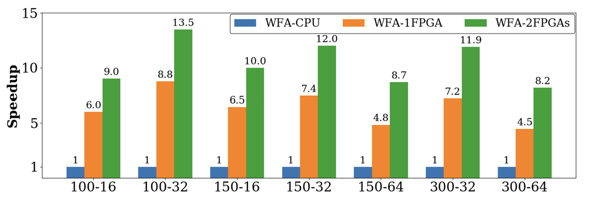
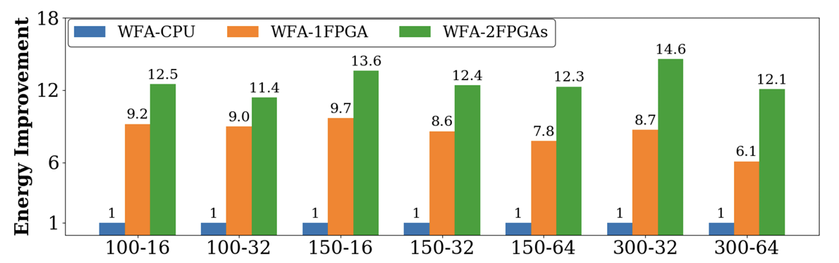
We evaluate the proposed WFA accelerator with different designs for typical read lengths and error score values on a high performance system with a POWER9 CPU and 2 FPGAs. Compared to the reference WFA CPU-only implementation [10], the FPGA accelerator achieves speedups of 4.5x to 8.8x with 1 FPGA, and of 8.2x to 13.5x with 2 FPGAs, while reducing the energy-to-solution by 6.1x to 9.7x with 1 FPGA, and by 11.4x to 14.6x with 2 FPGAs.
This paper is organized as follows: Section II introduces the background on read alignment and the WFA algorithm. Then, Section III presents the co-designed accelerator, which is evaluated in Section IV. Section V discusses the related work. Finally, Section VI remarks the conclusions of this work.
II. BACKGROUND
A. Read Mappers and Pairwise Alignment
Sequence-data analysis pipelines require locating the input sequences into a reference genome using a read mapper [11], [12]. Due to the large scale of genomic databases, read mappers are usually guided by seeding or filtering strategies that narrow down the search to a few candidate locations [1]–[5]. Then, each candidate location is aligned against the input sequence to assess the similarity between the two sequences.
Pairwise alignment of sequences is implemented using one of the many variants of the SW algorithm [6]. In biology, the SWG variant [8] is commonly preferred due to its ability to capture critical properties when comparing biological sequences. The SWG algorithm implements the gap-affine distance of two sequences for a given set of penalty scores (i.e., a match, mismatch, o gap-opening, and e gap-extension). All SWG algorithms are based on DP techniques and require quadratic time and memory, proportional to the sequence length. Despite its computational complexity, SWG is still the most accurate and widely used algorithm for biological sequence comparison.
B. Wavefront Alignment Algorithm
Very recently, the novel WFA pairwise alignment algorithm has been proposed [7]. Unlike other approaches, the WFA algorithm proposes an alternative encoding of the DP-matrix, shown in Equation 1, and an efficient algorithm to compute partial alignments with an increasing score. As a result, the WFA algorithm computes the cells of the DP-matrix by increasing score and only needs to compute a minimal number of cells to find the optimal alignment.
Basically, the WFA algorithm computes three offset vectors of increasing length per each score value. Instead of encoding the alignment score of the DP-matrix as the SWG algorithm, the WFA algorithm encodes the diagonal offset from the leftmost column of the DP-matrix to the farthermost cell that has score . The wavefront vectors , , and track alignments that end with an insertion, a deletion, or a match/mismatch, respectively. Starting from , the WFA algorithm computes wavefront vectors for increasing scores applying two operators: extend() and compute().
First, the operator extend() increases each offset of the wavefront vector according to the number of contiguous matching characters between the sequences. That is, for each diagonal offset in the wavefront vector, the algorithm computes the corresponding positions and in the DP-matrix. Then, it computes the number of contiguous matching characters between the sequences starting from and , respectively. Note that, given a zero match penalty (), the score along the diagonal remains constant. That is, matches between the sequences do not penalize the alignment score.
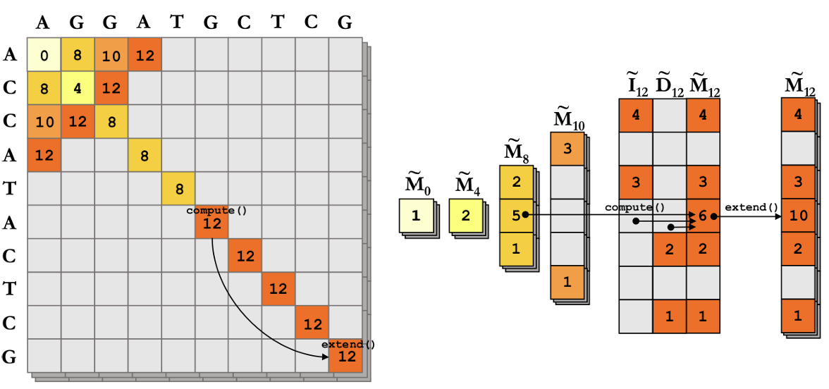
Once the offsets of the wavefront vector have been extended, the operator compute() computes the next wavefront vectors using Equation 1, for a given set of penalty scores under the gap-affine distance.
The WFA algorithm iterates over extend() and compute() until a wavefront, with score , reaches the end of both sequences. Hence, the optimal alignment has score . Then, the WFA retrieves the alignment CIGAR. From the optimal alignment offset , the algorithm traces the wavefront vectors back to the initial wavefront . For that, the operator backtrace() computes which values from Equation 1 generated each offset towards the optimal alignment.
Fig. 1 shows an example of aligning two sequences using the WFA algorithm, with penalties , and the corresponding cells in the DP-matrix using the classical SWG algorithm. The example depicts the detailed computation of the wavefront vector . First, Equation 1 is applied using the offsets from wavefront vectors , , and . For each resulting offset on , the operator extend() is used to compute exact matches along each diagonal. For instance, the offset , which corresponds to positions and in the DP-matrix, is extended 4 positions (i.e., ) as both sequences match the same substring "CTCG" from positions and , respectively.
As a result, the WFA algorithm runs in time, proportional to the sequence length and the alignment score between them . Unlike the SWG algorithm, the WFA algorithm performs simple and independent operations over the elements of the wavefronts, taking advantage of matching regions between the sequences to accelerate the alignment computation, while using a regular computational pattern. These properties make the WFA algorithm an efficient alternative to classic pairwise alignment methods, suitable for the design of efficient FPGA-based accelerators.
III. WFA Accelerator method
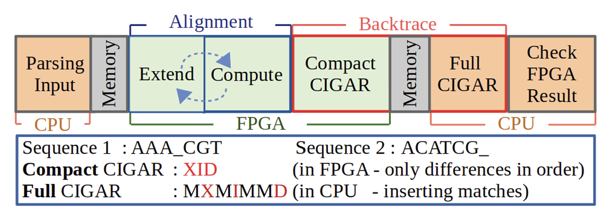
This section presents the proposed WFA accelerator. Fig. 2 shows the accelerator steps. First, the CPU parses the input files and stores them in the memory. Then, the FPGA reads the data, computes the alignments by iteratively performing the extend and compute steps, and writes the results to the memory in compact CIGAR form. After that, multiple CPU threads read and check the FPGA results and finish the backtrace step by unpacking the compact CIGARs to full CIGARs.
In our experiments with the reference CPU-only implementation of the WFA algorithm [10], the extend, compute and backtrace steps are responsible for around 50%, 45%, and 5% of the total execution time, respectively. Hence, offloading the extend and compute steps to the FPGA is crucial to accelerate the algorithm. In addition, offloading the backtrace step to the FPGA is also beneficial because, although this step has a small weight on the total execution time, it requires reading the whole data of all the wavefronts. Thus, to minimize bandwidth-bound data transfers between the CPU and the FPGA, the presented accelerator innovatively divides the backtrace step in two parts, one in the FPGA that computes the CIGARs in a compact form of only 8 bytes, and one in the CPU that unpacks the compact CIGARs and generates the full CIGARs. An example of a compact and a full CIGAR is shown in Fig. 2.
The FPGA design is composed of three main modules, as shown in Fig. 3. The Aligner module implements the main computational steps of the WFA algorithm. A configurable number of Aligners can be instantiated in the design so they process alignments in parallel. The Extractor module distributes sequences among the Aligners and the Collector module gathers results from them.
A. Extractor Module
The Extractor module distributes sequences among Aligners. This module has two states, Extract and Assign. The first state reads data from memory and extracts the DNA sequences, their IDs, and their lengths. The second state compresses the sequences by mapping each base to two bits and sequentially packs them in groups of 8 bases. When an Aligner becomes idle, the Extractor module assigns it one pair of sequences along with their lengths and IDs to process the alignment.

B. Collector Module
The Collector module collects the results of the Aligners and writes them to memory. The result of each Aligner is 16 bytes, while the FPGA data width is 128 bytes. Thus, the Collector module packs 8 results of each Aligner in one 128-byte word and then sends it to the CPU. A Scheduler handles the order in which the results of the different Aligners are sent.
C. Aligner Module
The Aligner module computes the sequences alignment. Each Aligner contains a configurable number of Extend and Compute sub-modules, a Backtrace sub-module, and a Controller sub-module that controls the operations and the data flow. The Extend and Compute sub-modules operate sequentially multiple times, as the output of one is the input of the other one. At the end, the Backtrace sub-module computes the compact CIGAR. Although these steps are executed sequentially, they are pipelined and internally parallelized.
- Aligner Parallel Structure: The parallel operation of the Aligners is achieved by dividing a wavefront matrix in independent parts. A wavefront matrix, as shown in Fig. 4(a), is a structure that unifies all the wavefront vectors of a given type . The values stored in the cells of the matrix are called offsets. The X axis of the wavefront matrix represents the distances, and each column of the matrix stores the wavefront vector for the corresponding distance (i.e., the column 0 of the wavefront matrix stores the wavefront vector . The Y axis is defined at compile time with a parameter called , which limits the maximum supported error score between sequences and sets the range of the Y axis from to . Since the length of the wavefront vectors increases with the distance, some cells of the wavefront matrix are invalid. In the example of Fig. 4(a), valid cells are marked with an X. Each column also has a Null tag that indicates if all the cells of that column are invalid.
The proposed accelerator exploits parallelism by computing all the values in a column of a wavefront matrix at the same time. For a given distance, the corresponding frame columns in the 3 wavefront matrices can be calculated in parallel, as they only depend on the previously calculated columns of the wavefront matrices (see Equation 1). We define window as the set of columns of a wavefront matrix that are needed to compute a given column. The rightmost column of a window, called frame column, is the one being processed, and the other columns of the window are needed as inputs to compute the frame column. The width of the windows depends on the penalty scores. For typical penalties , the computation of the frame column requires 2, 2 and 8 previous columns of the , , and wavefront matrices, respectively. When all the offsets of a frame column are calculated, all the columns of the window are shifted to the left and the leftmost one is discarded. This allows to reduce the FPGA resource utilization, as we only need to keep a limited number of columns of the wavefront matrices. The windows of the wavefront matrices are implemented as 2D-arrays of 8-bit elements to provide concurrent and fast access to the cells.
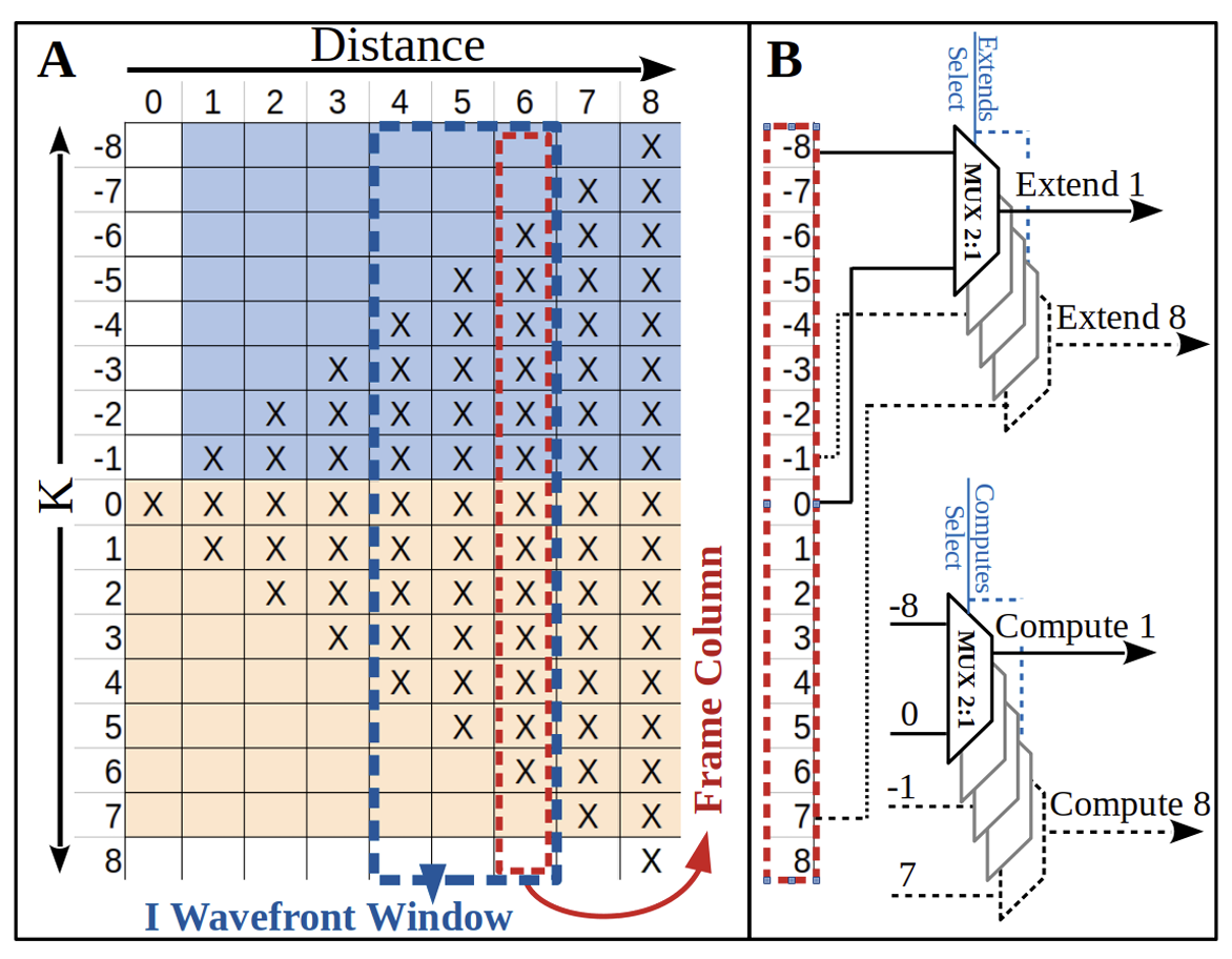
To compute a frame column, each of its cells is fed to a configurable number of Extend and Compute sub-modules, 8 of each in our setup. Note that the number of Extend and Compute sub-modules can be lower than the number of cells in a frame column, so the computation of the frame column can take several cycles. To efficiently use the FPGA resources, we restrict the possible inputs of the multiplexers that pass the offsets of the frame column to the Extend and Compute modules. In the example of Fig. 4(b), the offsets of cells -8 and 0 are inputs of the first Extend and Compute sub-modules, cells -7 and 1 are inputs of the second sub-modules, and so on. In Fig. 4(a) the colors represent the cycle in which each cell is processed. In the example, the frame column of distance 6 has 13 valid cells, and the computation of the cells in rows to is performed in the first cycle, while the computation of the cells in rows to are performed in the second cycle. We pipeline the processing of frame columns that require more than one cycle by first performing the compute for 8 cells and, while these 8 cells are extended, the next 8 cells are computed.
The next subsections explain in detail the architecture of the Aligner module and its sub-modules, shown in Fig. 5.
- Extend Sub-module: The Extend sub-module receives the offset of a cell, its position and a start signal. From these inputs, the Extend sub-module calculates the initial positions in sequence 1 and sequence 2, compares the bases of both sequences starting from the initial positions until a mismatch is found, and returns the number of matching bases.
To increase the speed of the design and minimize resources, the sequences are compared in blocks of 8 bases. To do so, the Extractor module packs blocks of 8 bases in an array of registers. However, each base of sequence 1 can be compared with any base of the sequence 2, and their positions may not be at the boundaries of the blocks of 8 bases. For this reason, 2 blocks of 8 bases of each sequence are passed to the Extend sub-module, which uses 2 multiplexers for each sequence to select the 8 bases that need to be compared. The selected 16 bases of each sequence are then concatenated and passed to a shift register that aligns them to the comparator input. The design is pipelined in such a way that the comparator compares 8 bases of the sequences at each clock cycle.
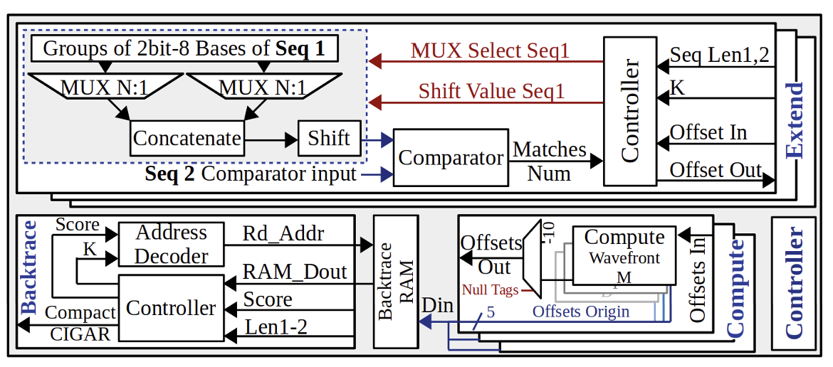
The extend operation continues until a mismatch is found. Then the Extend sub-module returns the number of matches and the new offset for the cell. The new offsets are stored in the rightmost column of wavefront window. After extending a column, if the alignment has not reached the end of the sequences and has not reached the maximum value, the Controller moves the window to the right, increases the score by 1, and extends by 1 from both ends.
- Compute Sub-module: After the extend step, the compute step determines the new offset of a cell of each wavefront frame column by comparing some of the previously calculated offsets of previous columns, as described in Equation 1.
The Compute sub-module is also in charge of managing the Null tags of the columns of the wavefront matrices. The Null tag of the frame column is determined by the Null tags of the input columns that are used to compute the frame column. If the Null tag of any of the input columns is not set, the Null tag of the frame column is set to 0 and the offsets are computed normally. Otherwise, the Null tag of the frame column is set to 1, a negative value is returned, and the upcoming extend operation is skipped because the extend of an invalid offset always returns the same offset.
This sub-module also tracks the origin of each computed cell in a Backtrace RAM, as the backtrace step requires this information. As shown in Equation 1, the origin of a cell in the , , and wavefronts matrices can come from 2, 2 and 5 positions, respectively, so we need 1, 1 and 3 bits to store them. At the end of the compute step, the origins of the computed cells are concatenated in 5 bits. Since 8 Compute sub-modules process 8 cells in parallel, the width of the Backtrace RAM is 40 bits, and a depth of 250 words is needed to support values of up to . The write address of the Backtrace RAM is controlled by the Controller sub-module of the Aligner.
TABLE I
DIFFERENT FPGA DESIGNS, THEIR INPUTS, RESOURCE UTILIZATION AND NUMBER OF ALIGNERS IN EACH FPGA.
| FPGA Design Len - K | Input Set Len - Avg K | LUT (%) | FF (%) | BRAM (%) | Aligners Num |
|---|---|---|---|---|---|
| 100 - 16 | 100 - 12 | 88 | 26 | 9 | 100 |
| 100 - 32 | 100 - 24 | 91 | 33 | 8 | 80 |
| 150 - 16 | 150 - 12 | 84 | 26 | 8 | 80 |
| 150 - 32 | 150 - 25 | 86 | 32 | 7 | 64 |
| 150 - 64 | 150 - 45 | 86 | 37 | 6 | 45 |
| 300 - 32 | 300 - 26 | 87 | 30 | 7 | 55 |
| 300 - 64 | 300 - 49 | 90 | 37 | 6 | 40 |
- Backtrace Sub-module: At the end of alignment, the backtrace determines the mismatches, insertions and deletions that have to be applied to one sequence to make it identical to the other sequence. For this step we propose a novel hardware/software co-designed technique that reduces the amount of memory required by the algorithm and avoids doing a traditional memory-bound backtrace. On the FPGA side, the Controller of the Backtrace sub-module receives the final score, the difference in the length of sequences, and the output stored in the Backtrace RAM. With these values it calculates the new K and score and it passes them to the Address Decoder to find the Backtrace RAM addresses of the previous location of the last cell. This process is iteratively repeated until the calculated score becomes 0 and the backtrace is done. Then, an 8-byte backtrace in compact CIGAR form is sent back to the CPU along with the sequence IDs, and the CPU then traverses the 2 sequences to unpack the backtrace in full CIGAR format. CPU threads can recover different backtraces in parallel, as they are completely independent processes.
IV. EVALUATION
A. Experimental Setup
We evaluate our proposal on a POWER9-based system with 512GB of RAM (16 32GB DDR4 DIMMs running at 2666MHz) and 2 FPGA boards. The POWER9 CPU has 16 cores with 4 threads per core running at 2.3GHz, and it is connected to 2 ADM-PCIE-9H7 FPGA boards with OpenCAPI, which provides coherent access to the host memory from the FPGAs and data transfer speeds of up to 22GB/s. The FPGAs are Xilinx Virtex UltraScale Plus XCVU37P-2E (FSVH2892), which run at 200MHz and have 2607k FFs, 1304k LUTs, 9024 DSPs, 70.9Mb BRAMs and 270Mb URAMs each. The evaluation reports results for executions with 1 and 2 FPGAs.
The proposed WFA accelerator is open source and publicly available [9]. The code allows to configure the sequence length and the maximum K of the FPGA design to better meet the input set characteristics. For the experimentation, we use 7 FPGA designs with different configurations of sequence lengths and K values representative of state-of-the-art sequencing technologies. Table I describes the 7 designs, showing their maximum sequence lengths and Ks, their input sets, their resource utilization, and the number of parallel aligners that fit in each FPGA. The parameters of the input sets are representative of current sequencing platforms [13]. Using the same methodology as in related studies [7], [14]–[16], we randomly generate 7 input sets with different maximum sequence lengths and values and we feed them to their corresponding FPGA design. Each input set contains 10 million pairs of sequences with random mismatches, insertions and deletions. Note that, given a maximum sequence length and , an FPGA design can correctly process any input containing shorter sequences for smaller . Nevertheless, a tailored instantiation requires less space in the FPGA and maximizes the number of aligners that can fit in the FPGA.
The baseline used in the evaluation is the reference CPU implementation of the WFA algorithm proposed by Marco-Sola et al. [7], which is open source and publicly available [10]. In the evaluation we refer to this CPU-only baseline implementation as WFA-CPU. In all the experiments we do an exploration of the number of CPU threads (from 1 to 64) on the FPGA designs and the WFA-CPU implementation, and we report the execution time of the best performing number of threads unless stated otherwise. The time and energy measurements include the data transfers between the CPU and the FPGAs, and parsing the input files is not included in the measurements of any execution (FPGA or WFA-CPU).
Compared to a reference multithreaded CPU implementation of the traditional SWG [8], the WFA-CPU achieves speedups of 8.4× to 53.3× for the 7 input sets we consider, and the proposed accelerator outperforms it by 42.6× to 383.8× with 1 FPGA and by 76.6× to 634.3× with 2 FPGAs. In addition, compared to a Banded Smith-Waterman heuristic method [10] that does not perform the backtrace, the proposed WFA accelerator achieves speedups of 37.4× to 93.5× with 1 FPGA and of 55.9× to 154.8× with 2 FPGAs for the same 7 input sets considered in this work.
B. Results
Fig. 6 shows the speedup achieved by the 7 different designs of the proposed FPGA accelerator compared to the WFA-CPU. The different FPGA designs achieve speedups of 4.5× to 8.8× with 1 FPGA, and of 8.2× to 13.5× when the 2 FPGAs in the system are used. The lowest speedups belong to the designs with biggest Ks. This happens because the size of the aligner module increases as K grows, so fewer aligners fit in the FPGA and fewer sequences are aligned in parallel. Using 2 FPGAs increases the speedup by a factor of 1.5× to 1.8× compared to 1 FPGA. Using 2 FPGAs doubles the speed of FPGA part of the co-design, but the time of CPU part remains unchanged, so the whole execution time is not halved.
TABLE II
DURATION (CLK) OF ALIGNMENT AND BACKTRACE OF ONE SEQUENCE PAIR AND MAXIMUM POSSIBLE ALIGNERS IN 1 FPGA.
| FPGA Design | Alignment (clk) | Backtrace (clk) | Total (clk) | Extract input (clk) | Max Aligners |
|---|---|---|---|---|---|
| 100 - 16 | 185 | 15 | 200 | 3 | 67 |
| 100 - 32 | 265 | 23 | 588 | 3 | 196 |
| 150 - 16 | 185 | 15 | 200 | 4 | 50 |
| 150 - 32 | 265 | 23 | 588 | 4 | 147 |
| 150 - 64 | 1900 | 39 | 1939 | 4 | 485 |
| 300 - 32 | 265 | 23 | 588 | 6 | 98 |
| 300 - 64 | 1900 | 39 | 1939 | 6 | 324 |
Table II shows, for each FPGA design, the maximum possible number of aligners before saturating the OpenCAPI bandwidth. The table indicates, for each design, how many FPGA clock cycles are needed to do the alignment, the backtrace, and to extract one pair of sequences. From these numbers, the maximum possible aligners in each system is calculated and shown in the last column. In this test we feed each design with inputs with values equal to the maximum supported in each design. If these designs are fed with inputs with smaller , the bandwidth is saturated with even fewer aligners. As shown in Table I, the design with sequence length 150 and has 80 aligners per FPGA, although Table II shows that this design saturates the bandwidth with 50 aligners. So, in this design, adding more than 50 aligners per FPGA does not provide any benefit because the Extractor module cannot feed them with data on time due to bandwidth limitations.
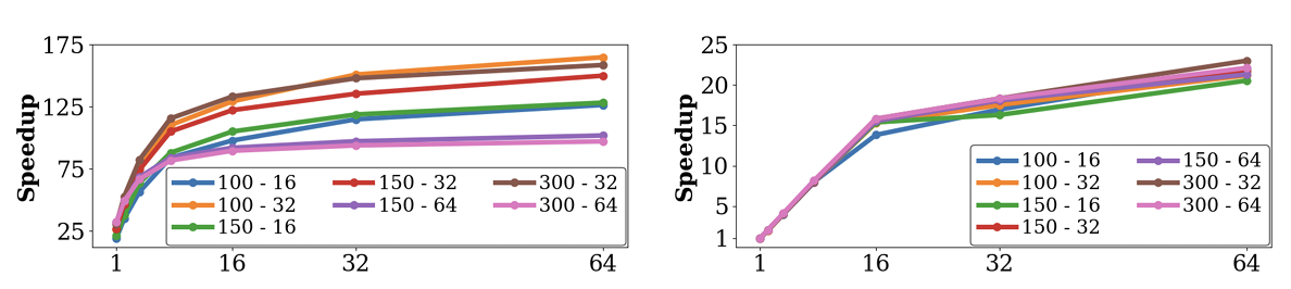
Fig. 7 shows the scalability of multi-threaded runs of the FPGA accelerator with 1 FPGA and of the WFA-CPU. All the speedups are computed over the single threaded execution of the WFA-CPU. The POWER9 CPU has 64 threads, so the scalability of the WFA-CPU and the FPGA designs saturates at that point. In single threaded runs, the FPGA designs achieve speedups over WFA-CPU of 19× to 32×. The scalability of the WFA-CPU is linear up to 16 threads but, after that point, the parallel efficiency drops because the threads have to share the resources of the CPU cores. The scalability of the c-designs is less effective because, when increasing the number of threads, the time spent in the CPU part decreases and, hence, the constant thread-independent FPGA time dominates the total execution time.
Next we study the impact of encountering input pairs of sequences with larger than the maximum supported in the FPGA designs. We feed the FPGA design with maximum sequence length of 150 and with an input in which 90% of the sequences have lower than 32 and the other 10% have larger than 32, so the alignment of these 10% of sequences has to be done in the CPU. The best execution times of the FPGA design are 1318ms with 1 FPGA and 1030ms with 2 FPGAs, while the fastest WFA-CPU execution for this input is 4500ms, so the FPGA design achieves speedups of and with 1 and 2 FPGAs, respectively.
Finally, Fig. 8 shows the improvement in energy consumption of the different FPGA designs compared to the WFA-CPU. To report meaningful power consumption measurements, in this experiment we repeat the alignment of the same input set several times so the fastest execution takes at least 30 seconds. For each input set, the number of repetitions and the total amount of work to be performed is the same in the WFA-CPU and the FPGA design. We use in-band readings from Linux to the OCC (On Chip Controller) [17] to measure the power consumption of the whole node (CPU and FPGAs). Results show that the different FPGA designs consume significantly less energy than the WFA-CPU, with energy improvements of to with 1 FPGA and of to with 2 FPGAs.
V. RELATED WORK
In recent years, many accelerators have been proposed to improve the performance of read mappers. These accelerators leverage different technologies such as in-memory computations [18]–[23], GPUs [24]–[29], ASICs [15], [30]–[35], and FPGAs [14]–[16], [32]–[64].
In-memory computation is a promising technique to accelerate read alignment, either using the SW algorithm [19], [21] or the Needleman-Wunsch (NW) algorithm [18]. Similarly, GPUs can also be leveraged to accelerate the SW algorithm [24], [28], [29], while other works propose GPU-based accelerators for both the SW and the NW algorithms [25], [26].
Many ASIC and FPGA-based methods have been proposed to accelerate the SW algorithm. As a result, some surveys [65]–[67] have been published summarizing the many contributions done over the years. In addition, many production-ready bioinformatics tools already incorporate custom FPGA accelerators [35]–[38], [45], [52], [53].
Some of the earlier works on sequence alignment tried to fully optimize the FPGA LUTs by doing custom optimizations using simple cost models, like the edit-distance, the Levenshtein distance [39] or being limited to compute the longest common subsequence [40]. Despite their good performance, these solutions do not fulfill the requirements of modern bioinformatics tools due to algorithmic limitations.
Other FPGA-based proposals tackled the problem of accelerating the SW algorithm using linear gap penalties [16], [41]–[51]. The design of these accelerators has improved from optimized designs based on systolic architectures [41], [45], [46], [49] and custom FPGA designs to large-scale accelerators running on supercomputing infrastructures [47], [48]. Nevertheless, these solutions lack the flexibility to meet the requirements of many biological applications. For this reason, FPGA accelerators that fully implement the gap-affine model (i.e., the SWG algorithm) are usually preferred [14], [15], [32]–[35], [53]–[64].
Other works propose to accelerate SWG approximate methods such as banded SWG. These heuristic methods are usually employed to align long reads [15], [32], [33], although some works also apply them to short reads [30], [35]. The main limitation of these approaches is that the result of the algorithms is not guaranteed to be the optimal one, so they trade speed for accuracy.
Another problem of the gap-affine model is the complexity of producing the full alignment. For this reason, some accelerators proposed in the literature are limited to compute the alignment score [54], [55], but not the CIGAR. In contrast, other designs offer more flexibility and allow the computation of the full CIGAR alignment at the expense of lower performance [31], [56], [63].
Cell Updates Per Second (CUPS) is a common metric used to measure the performance of SW algorithms, regardless of their target devices and implementation specifics. CUPS represent the number of cells from the DP-matrix computed per second. Table III compares the most relevant FPGA accelerators for the exact gap-affine SWG algorithm. It is important to note that the WFA algorithm avoids the full computation of the DP-matrix. So, for a fair comparison, we compute the CUPS considering the equivalent number of DP cells that the SWG algorithm would need to compute the optimal alignment; that is, to generate the same results as the WFA algorithm. Altogether, Table III shows that our WFA accelerator achieves 9.7x and 16.1x more CUPS than the best FPGA solution in the state-of-the-art.
VI. CONCLUSIONS
This paper presents an efficient hardware/software co-designed accelerator of the WFA algorithm. The proposed approach consists of an FPGA design that accelerates the pairwise alignment of sequences and calculates the backtrace in compact CIGAR, while the CPU part gathers the compact CIGARs and recovers the complete alignment in full CIGAR form. Results show that, for different combinations of sequence lengths and error rates, the presented WFA accelerator achieves speedups over the reference WFA CPU implementation of with 1 FPGA, and of with 2 FPGAs. The proposed accelerator also reduces the energy-to-solution by with 1 FPGA and by with 2 FPGAs.
TABLE III
PEAK GCUPS OF DIFFERENT SWG FPGA ACCELERATED METHODS.
| Paper | Year | Device | Freq. (MHz) | GCUPS |
|---|---|---|---|---|
| Ours | 2021 | 2x Xilinx Virtex U+ XCVU37P | 200 | 2073.7 |
| Ours | 2021 | 1x Xilinx Virtex U+ XCVU37P | 200 | 1251.7 |
| [56] | 2019 | Xilinx VU9P Ultrascale | 200 | |
| [57] | 2018 | Altera Stratix V | n/a | 58.4 |
| [14] | 2018 | Xilinx Virtex7 XC7VX485T | 200 | 105.9 |
| [54] | 2018 | Intel Arria 10 GX | n/a | |
| [64] | 2013 | Altera Stratix V A7 | 200 | 24.7 |
| [58] | 2011 | Xilinx XC5VLX330T | 130 | |
| [63] | 2009 | Xilinx XC2V6000-4 | 47.6 | 8.0 |
| [59] | 2007 | Altera EPS1S30 | 82 | 6.6 |
* GCUPs for this accelerator are not reported explicitly, we calculate them from the data provided in the original paper [56].
** This accelerator does not perform backtrace.
*** This accelerator reports the theoretical FPGA peak performance, without considering I/O limitations.
ACKNOWLEDGMENT
This work has been supported by the European HiPEAC Network of Excellence, by the Spanish Ministry of Science and Innovation (contract PID2019-107255GB-C21/AEI/10.13039/501100011033), by the Generalitat de Catalunya (contracts 2017-SGR-1414 and 2017-SGR-1328), by the IBM/BSC Deep Learning Center initiative, and by the DRAC project, which is co-financed by the European Union Regional Development Fund within the framework of the ERDF Operational Program of Catalonia 2014-2020 with a grant of 50% of total eligible cost. Ll. Alvarez has been partially supported by the Spanish Ministry of Economy, Industry and Competitiveness under the Juan de la Cierva Formacion fellowship No. FJCI-2016-30984. M. Moreto has been partially supported by the Spanish Ministry of Economy, Industry and Competitiveness under Ramon y Cajal fellowship No. RYC-2016-21104.
REFERENCES
[1] S. F. Altschul, W. Gish, W. Miller, E. W. Myers, and D. J. Lipman, “Basic local alignment search tool,” Journal of Molecular Biology, vol. 215, no. 3, pp. 403–410, 1990.
[2] H. Li, “Aligning sequence reads, clone sequences and assembly contigs with BWA-MEM,” arXiv preprint arXiv:1303.3997, 2013.
[3] —, “Minimap2: pairwise alignment for nucleotide sequences,” Bioinformatics, vol. 34, no. 18, pp. 3094–3100, 2018.
[4] S. Marco-Sola, M. Sammeth, R. Guigó, and P. Ribeca, "The GEM mapper: fast, accurate and versatile alignment by filtration," Nature methods, vol. 9, no. 12, p. 1185, 2012.
[5] S. Marco-Sola and P. Ribeca, “Efficient alignment of Illumina-like high-throughput sequencing reads with the genomic multi-tool (GEM) mapper,” Current Protocols in Bioinformatics, vol. 50, no. 1, pp. 11–13, 2015.
[6] T. F. Smith, M. S. Waterman et al., “Identification of common molecular subsequences,” Journal of Molecular Biology, vol. 147, no. 1, pp. 195–197, 1981.
[7] S. Marco-Sola, J. C. Moure, M. Moreto, and A. Espinosa, “Fast gap-affine pairwise alignment using the wavefront algorithm,” Bioinformatics, no. btaa777, pp. 1–8, 2020.
[8] O. Gotoh, "An improved algorithm for matching biological sequences," Journal of Molecular Biology, vol. 162, no. 3, pp. 705–708, 1982.
[9] [Online]. Available: https://gitlab.bsc.es/ahaghi/wfa_fpga_accelerator
[10] [Online]. Available: https://github.com/smarco/WFA
[11] M. A. DePristo, E. Banks, R. Poplin, K. V. Garimella, J. R. Maguire, C. Hartl, A. A. Philippakis, G. Del Angel, M. A. Rivas, M. Hanna et al., “A framework for variation discovery and genotyping using next-generation DNA sequencing data,” Nature genetics, vol. 43, no. 5, p. 491, 2011.
[12] N. A. Fonseca, J. Rung, A. Brazma, and J. C. Marioni, “Tools for mapping high-throughput sequencing data,” Bioinformatics, vol. 28, no. 24, pp. 3169–3177, 2012.
[13] H.-M. Kim, S. Jeon, O. Chung, J. H. Jun, H.-S. Kim, A. Blazyte, H.-Y. Lee, Y. Yu, Y. S. Cho, D. M. Bolser, and J. Bhak, “Comparative analysis of 7 short-read sequencing platforms using the Korean Reference Genome: MGI and Illumina sequencing benchmark for whole-genome sequencing,” GigaScience, vol. 10, no. 3, 03 2021, giab014. [Online]. Available: https://doi.org/10.1093/gigascience/giab014
[14] X. Fei, Z. Dan, L. Lina, M. Xin, and Z. Chunlei, “FPGASW: Accelerating large-scale Smith-Waterman sequence alignment application with backtracking on FPGA linear systolic array,” Interdisciplinary Sciences: Computational Life Sciences, vol. 10, no. 1, pp. 176–188, 2018.
[15] Y.-L. Liao, Y.-C. Li, N.-C. Chen, and Y.-C. Lu, “Adaptively banded Smith-Waterman algorithm for long reads and its hardware accelerator,” in International Conference on Application-specific Systems, Architectures and Processors (ASAP). IEEE, 2018, pp. 1-9.
[16] S. Lloyd and Q. O. Snell, “Hardware accelerated sequence alignment with traceback,” International Journal of Reconfigurable Computing, vol. 2009, 2009.
[17] T. Rosedahl, M. Broyles, C. Lefurgy, B. Christensen, and W. Feng, “Power/performance controlling techniques in OpenPOWER,” in International Conference on High Performance Computing. Springer, 2017, pp. 275–289.
[18] S. Gupta, M. Imani, B. Khaleghi, V. Kumar, and T. Rosing, “RAPID: A. ReRAM processing in-memory architecture for DNA sequence alignment,” in 2019 IEEE/ACM International Symposium on Low Power Electronics and Design (ISLPED). IEEE, 2019, pp. 1–6.
[19] R. Kaplan, L. Yavits, and R. Ginosasr, “BioSEAL: In-memory biological sequence alignment accelerator for large-scale genomic data,” in Proceedings of the 13th ACM International Systems and Storage Conference, 2020, pp. 36–48.
[20] F. Zokaee, H. R. Zarandi, and L. Jiang, “Aligner: A process-in-memory architecture for short read alignment in reRAMs,” IEEE Computer Architecture Letters, vol. 17, no. 2, pp. 237–240, 2018.
[21] R. Kaplan, L. Yavits, R. Ginosar, and U. Weiser, “A resistive CAM processing-in-storage architecture for DNA sequence alignment,” IEEE Micro, vol. 37, no. 4, pp. 20–28, 2017.
[22] W. Huangfu, S. Li, X. Hu, and Y. Xie, "Radar: a 3D-reRAM based DNA alignment accelerator architecture," in Proceedings of the 55th Annual Design Automation Conference, 2018, pp. 1–6.
[23] Z. I. Chowdhury, M. Zabihi, S. K. Khatamifard, Z. Zhao, S. Resch, M. Razaviyayn, J.-P. Wang, S. S. Sapatnekar, and U. R. Karpuzcu, “A DNA read alignment accelerator based on computational RAM,” IEEE Journal on Exploratory Solid-State Computational Devices and Circuits, vol. 6, no. 1, pp. 80–88, 2020.
[24] Y. Liu, A. Wirawan, and B. Schmidt, “CUDASW++ 3.0: accelerating Smith-Waterman protein database search by coupling CPU and GPU-SIMD instructions,” BMC bioinformatics, vol. 14, no. 1, pp. 1–10, 2013.
[25] J. Blazewicz, W. Frohmberg, M. Kierzynka, E. Pesch, and P. Wojciechowski, “Protein alignment algorithms with an efficient backtracking routine on multiple GPUs,” BMC bioinformatics, vol. 12, no. 1, pp. 1–17, 2011.
[26] M. A. Shehab, A. A. Ghadawi, L. Alawneh, M. Al-Ayyoub, and Y. Jararweh, “A hybrid CPU-GPU implementation to accelerate multiple pairwise protein sequence alignment,” in 2017 8th International Conference on Information and Communication Systems (ICICS). IEEE, 2017, pp. 12–17.
[27] S. Rani and O. Gupta, "CLUS_GPU-BLASTP: accelerated protein sequence alignment using GPU-enabled cluster," The Journal of Super-computing, vol. 73, no. 10, pp. 4580–4595, 2017.
[28] S. Warris, N. R. N. Timal, M. Kempenaar, A. M. Poortinga, H. van de Geest, A. L. Varbanescu, and J.-P. Nap, “pyPaSWAS: Python-based multi-core CPU and GPU sequence alignment,” PLoS One, vol. 13, no. 1, p. e0190279, 2018.
[29] L.-T. Huang, C.-C. Wu, L.-F. Lai, and Y.-J. Li, "Improving the mapping of smith-waterman sequence database searches onto CUDA-enabled GPUs," BioMed research international, vol. 2015, 2015.
[30] D. Fujiki, A. Subramanian, T. Zhang, Y. Zeng, R. Das, D. Blaauw, and S. Narayanasamy, "Genax: A genome sequencing accelerator," in 2018 ACM/IEEE 45th Annual International Symposium on Computer Architecture (ISCA). IEEE, 2018, pp. 69–82.
[31] J.-P. Wu, Y.-C. Lin, Y.-W. Wu, S.-W. Hsieh, C.-H. Tai, and Y.-C. Lu, "A memory-efficient accelerator for DNA sequence alignment with two-piece affine gap tracebacks," in 2021 IEEE International Symposium on Circuits and Systems (ISCAS). IEEE, 2021, pp. 1-4.
[32] Y. Turakhia, G. Bejerano, and W. J. Dally, "Darwin: A genomics co-processor provides up to 15,000x acceleration on long read assembly," ACM SIGPLAN Notices, vol. 53, no. 2, pp. 199–213, 2018.
[33] Y. Turakhia, K. J. Zheng, G. Bejerano, and W. J. Dally, “Darwin: A hardware-acceleration framework for genomic sequence alignment,” bioRxiv, p. 092171, 2017.
[34] Y. Turakhia, S. D. Goenka, G. Bejerano, and W. J. Dally, "Darwin-WGA: A co-processor provides increased sensitivity in whole genome alignments with high speedup," in 2019 IEEE International Symposium on High Performance Computer Architecture (HPCA). IEEE, 2019, pp. 359–372.
[35] D. Fujiki, S. Wu, N. Ozog, K. Goliya, D. Blaauw, S. Narayanasamy, and R. Das, “SeedEx: A genome sequencing accelerator for optimal alignments in subminimal space,” in 2020 53rd Annual IEEE/ACM International Symposium on Microarchitecture (MICRO). IEEE, 2020, pp. 937–950.
[36] B. Hill, J. Smith, G. Srinivasa, K. Sonmez, A. Sirasao, A. Gupta, and M. Mukherjee, “Precision medicine and FPGA technology: Challenges and opportunities,” in 2017 IEEE 60th International Midwest Symposium on Circuits and Systems (MWSCAS). IEEE, 2017, pp. 655–658.
[37] L. Guo, J. Lau, Z. Ruan, P. Wei, and J. Cong, “Hardware acceleration of long read pairwise overlapping in genome sequencing: A race between FPGA and GPU,” in International Symposium on Field-Programmable Custom Computing Machines (FCCM), 2019, pp. 127–135.
[38] J. Arram, K. H. Tsoi, W. Luk, and P. Jiang, “Reconfigurable acceleration of short read mapping,” in International Symposium on Field-Programmable Custom Computing Machines (FCCM), 2013, pp. 210–217.
[39] S. S. Banerjee, M. El-Hadedy, J. B. Lim, Z. T. Kalbarczyk, D. Chen, S. S. Lumetta, and R. K. Iyer, "Asap: Accelerated short-read alignment on programmable hardware," IEEE Transactions on Computers, vol. 68, no. 3, pp. 331–346, 2018.
[40] C. A. Jorge, A. S. Nery, A. C. Melo, and A. Goldman, “A CPU-FPGA heterogeneous approach for biological sequence comparison using high-level synthesis,” Concurrency and Computation: Practice and Experience, p. e6007, 2020.
[41] R. B. Abdelhamid and Y. Yamaguchi, “A block-based systolic array on an HBM2 FPGA for DNA sequence alignment,” in International Symposium on Applied Reconfigurable Computing, 2020, pp. 298–313.
[42] E. Houtgast, V.-M. Sima, and Z. Al-Ars, “High performance streaming-Smith-Waterman implementation with implicit synchronization on intel FPGA using OpenCL,” in 2017 IEEE 17th International Conference on Bioinformatics and Bioengineering (BIBE). IEEE, 2017, pp. 492–496.
[43] L. Di Tucci, K. O'Brien, M. Blott, and M. D. Santambrogio, “Architectural optimizations for high performance and energy efficient Smith-Waterman implementation on FPGAs using OpenCL,” in Design, Automation & Test in Europe Conference (DATE), 2017, pp. 716–721.
[44] B. Strengholt and M. Brobbel, “Acceleration of the Smith-Waterman algorithm for DNA sequence alignment using an FPGA platform,” 2013.
[45] E. J. Houtgast, V.-M. Sima, K. Bertels, and Z. Al-Ars, "An FPGA-based systolic array to accelerate the BWA-MEM genomic mapping algorithm," in 2015 international conference on embedded computer systems: Architectures, modeling, and simulation (samos). IEEE, 2015, pp. 221-227.
[46] J. M. Marmolejo-Tejada, V. Trujillo-Olaya, C. P. Rentería-Mejía, and J. Velasco-Medina, "Hardware implementation of the Smith-Waterman algorithm using a systolic architecture," in 2014 IEEE 5th Latin American Symposium on Circuits and Systems. IEEE, 2014, pp. 1–4.
[47] L. Wienbrandt, "Bioinformatics applications on the FPGA-based high-performance computer RIVYERA," in High-Performance Computing Using FPGAs. Springer, 2013, pp. 81–103.
[48] E. Vermij, “Genetic sequence alignment on a supercomputing platform,” 2011.
[49] C. W. Yu, K. Kwong, K.-H. Lee, and P. H. W. Leong, "A Smith-Waterman systolic cell," in International Conference on Field Programmable Logic and Applications. Springer, 2003, pp. 375–384.
[50] K. Puttegowda, W. Worek, N. Pappas, A. Dandapani, P. Athanas, and A. Dickerman, “A run-time reconfigurable system for gene-sequence searching,” in 16th International Conference on VLSI Design, 2003. Proceedings. IEEE, 2003, pp. 561–566.
[51] T. V. Court and M. C. Herbordt, "Families of FPGA-based algorithms for approximate string matching." in ASAP, 2004, pp. 354–364.
[52] Y.-T. Chen, J. Cong, J. Lei, and P. Wei, “A novel high-throughput acceleration engine for read alignment,” in International Symposium on Field-Programmable Custom Computing Machines (FCCM), 2015, pp. 199–202.
[53] H.-C. Ng, S. Liu, I. Coleman, R. S. Chu, M.-C. Yue, and W. Luk, “Acceleration of short read alignment with runtime reconfiguration,” in 2020 International Conference on Field-Programmable Technology (ICFPT). IEEE, 2020, pp. 256–262.
[54] E. Rucci, C. Garcia, G. Botella, A. De Giusti, M. Naiouf, and M. Prieto-Matias, “SWIFOLD: Smith-Waterman implementation on FPGA with OpenCL for long DNA sequences,” BMC systems biology, vol. 12, no. 5, p. 96, 2018.
[55] C. Pham-Quoc, B. Kieu-Do, and T. N. Thinh, “A high-performance FPGA-based BWA-MEM DNA sequence alignment,” Concurrency and Computation: Practice and Experience, vol. 33, no. 2, p. e5328, 2021.
[56] K. Koliogeorgi, N. Voss, S. Fytraki, S. Xydis, G. Gaydadjiev, and D. Soudris, “Dataflow acceleration of Smith-Waterman with traceback for high throughput next generation sequencing,” in 2019 29th International Conference on Field Programmable Logic and Applications (FPL). IEEE, 2019, pp. 74–80.
[57] E. Rucci, C. Garcia, G. Botella, A. E. De Giusti, M. Naiouf, and M. Prieto-Matias, “OSWALD: OpenCL Smith-Waterman on altera’s FPGA for large protein databases,” The International Journal of High Performance Computing Applications, vol. 32, no. 3, pp. 337–350, 2018.
[58] Y. Yamaguchi, H. K. Tsoi, and W. Luk, “FPGA-based Smith-Waterman
algorithm: Analysis and novel design," in International Symposium on Applied Reconfigurable Computing. Springer, 2011, pp. 181–192.
[59] X. Jiang, X. Liu, L. Xu, P. Zhang, and N. Sun, “A reconfigurable accelerator for Smith-Waterman algorithm,” IEEE Transactions on Circuits and Systems II: Express Briefs, vol. 54, no. 12, pp. 1077–1081, 2007.
[60] I. T. Li, W. Shum, and K. Truong, "160-fold acceleration of the Smith-Waterman algorithm using a field programmable gate array (FPGA)," BMC bioinformatics, vol. 8, no. 1, p. 185, 2007.
[61] J. Allred, J. Coyne, W. Lynch, V. Natoli, J. Grecco, and J. Morrissette, "Smith-Waterman implementation on a FSB-FPGA module using the intel accelerator abstraction layer," in 2009 IEEE International Symposium on Parallel & Distributed Processing. IEEE, 2009, pp. 1–4.
[62] P. Zhang, G. Tan, and G. R. Gao, “Implementation of the Smith-Waterman algorithm on a reconfigurable supercomputing platform,” in International Workshop on High-Performance Reconfigurable Computing Technology and Applications (HPRCTA), 2007, pp. 39–48.
[63] K. Benkrid, Y. Liu, and A. Benkrid, “A highly parameterized and efficient FPGA-based skeleton for pairwise biological sequence alignment,” IEEE Transactions on Very Large Scale Integration (VLSI) Systems, vol. 17, no. 4, pp. 561–570, 2009.
[64] S. O. Settle et al., “High-performance dynamic programming on FPGAs with OpenCL,” in IEEE High Performance Extreme Computing Conference (HPEC), 2013, pp. 1–6.
[65] S. Salamat and T. Rosing, “FPGA acceleration of sequence alignment: A survey,” arXiv preprint arXiv:2002.02394, 2020.
[66] D. Nurdin, M. Isa, and S. Goh, "DNA sequence alignment: A review of hardware accelerators and a new core architecture," in International Conference on Electronic Design (ICED). IEEE, 2016, pp. 264–268.
[67] L. Hasan and Z. Al-Ars, "An overview of hardware-based acceleration of biological sequence alignment," Computational Biology and Applied Bioinformatics, pp. 187–202, 2011.