4.2 Deterministic latency
4.2.1 Introduction and general requirements
Many JESD204 systems contain various data processing elements that are distributed across different clock domains and lead to ambiguous delays through the interface. These ambiguities lead to nonrepeatable latencies across the link from power-up to power-up or over link-reestablishments. The JESD204 standard provides the option for what's called "deterministic latency" to avoid such ambiguity.
Deterministic latency across the link is defined from the parallel frame-based data input on the TX device to the parallel frame-based data output on the RX device. This latency across the link shall be repeatable from power-up cycle to power-up cycle and across link re-synchronization events, provided that the auxiliary timing signals meet the required specifications at the device inputs.
The frame-based input and output points for defining latency are at the interface between the transport layer and the application layer. Therefore, the implementation of the deterministic latency may partly or wholly take place in the transport layer or application layer.
The use of a local multiframe clock (LMFC) or local extended multiblock clock (LEMC) is required to achieve deterministic latency. The data in the TX and RX devices shall be aligned to the LMFC/LEMC in the following way:
In the TX device, the start of any multiframe or extended multiblock shall be initiated simultaneously across all lanes at a well-defined moment in time.
- The well-defined moment in time for TX transmission is a deterministic period of time from all active LMFC/LEMC edges.
In the RX device, a buffer shall exist to hold all lane data for release (i.e., data allowed to propagate) simultaneously at a well-defined moment in time.
- The well-defined moment in time for RX buffer release is a programmable number of steps after an active LMFC/LEMC edge. This programmable number of steps is referred to as the RX Buffer Delay (RBD).
- The full adjustment range of RBD shall cover the full size of the RX elastic buffer or at least one LMFC/LEMC cycle, whichever is smaller.
- The minimum size required for the RX elastic buffer corresponds to the maximum possible skew at skew point SP5 for the relevant subclass (see 4.3.8). The oldest data in the buffer available for release shall correspond to the start of a multiframe or extended multiblock.
- The RBD adjustment resolution shall not be greater than 255 steps.
- The RBD adjustment resolution shall be at least 16 steps. If more than one multiframe or multiblock per lane fits in the buffer, the RBD adjustment resolution shall be at least 16 steps per multiframe or multiblock.
The RBD adjustment is required to move the release of the elastic buffer away from any point in time that may lie within the range of lane data arrival skew (see example below). It must be possible, through the use of RBD, to select a release opportunity that does not lie in this range. Smaller and more numerous RBD adjustment steps are preferred to meet this requirement and to assist in selecting a release opportunity just after the latest possible lane arrival, which is useful to minimize total latency through the link. In order that the system implementer can select the optimum RBD value, the RX device shall be able to report over the control interface the arrival time of the multiframe or extended multiblock boundary relative to the active LMFC/LEMC edge for at least the slowest received lane.
The moments of generation of the multiframe or extended multiblock boundaries and release of the RX buffer mentioned above are related to the LMFC/LEMCs in the TX and RX devices. Thus, the achievement of deterministic latency with minimum uncertainty relies on achievement of a fixed offset between the LMFC/LEMCs within TX and RX devices. To achieve proper performance of the deterministic latency protocol, the period of the LMFC/LEMC, i.e., the duration of a multiframe or extended multiblock, must be larger than the maximum possible delay variation across any link or multipoint link.
To achieve deterministic latency for JESD204 links, the RX device must be able to buffer the incoming data of all lanes until the RX elastic buffer can be released. To release the elastic buffer, data must be present that corresponds to the start of a multiframe or extended multiblock for all active lanes. The buffer must be released after an active LMFC/LEMC edge according to the RBD value.
The selection of the moment to release the buffers in a JESD204C system is illustrated in the timing diagram of Figure 5. As part of the initial lane alignment, the TX device transmits a stream of /K/ characters, followed by an initial lane alignment sequence (ILAS). In this example, ILAS starts exactly on an active LMFC edge. The RX device will then detect the start of ILAS on each lane, and will feed this data into per-lane elastic buffers. The 'release opportunity' of these buffers is set to RBD character durations after each active LMFC edge. On the first release opportunity after the RX device receives valid ILAS data on all lanes, it will release all the elastic store buffers. The resulting data output from the RX device is aligned with a fixed latency across the link.
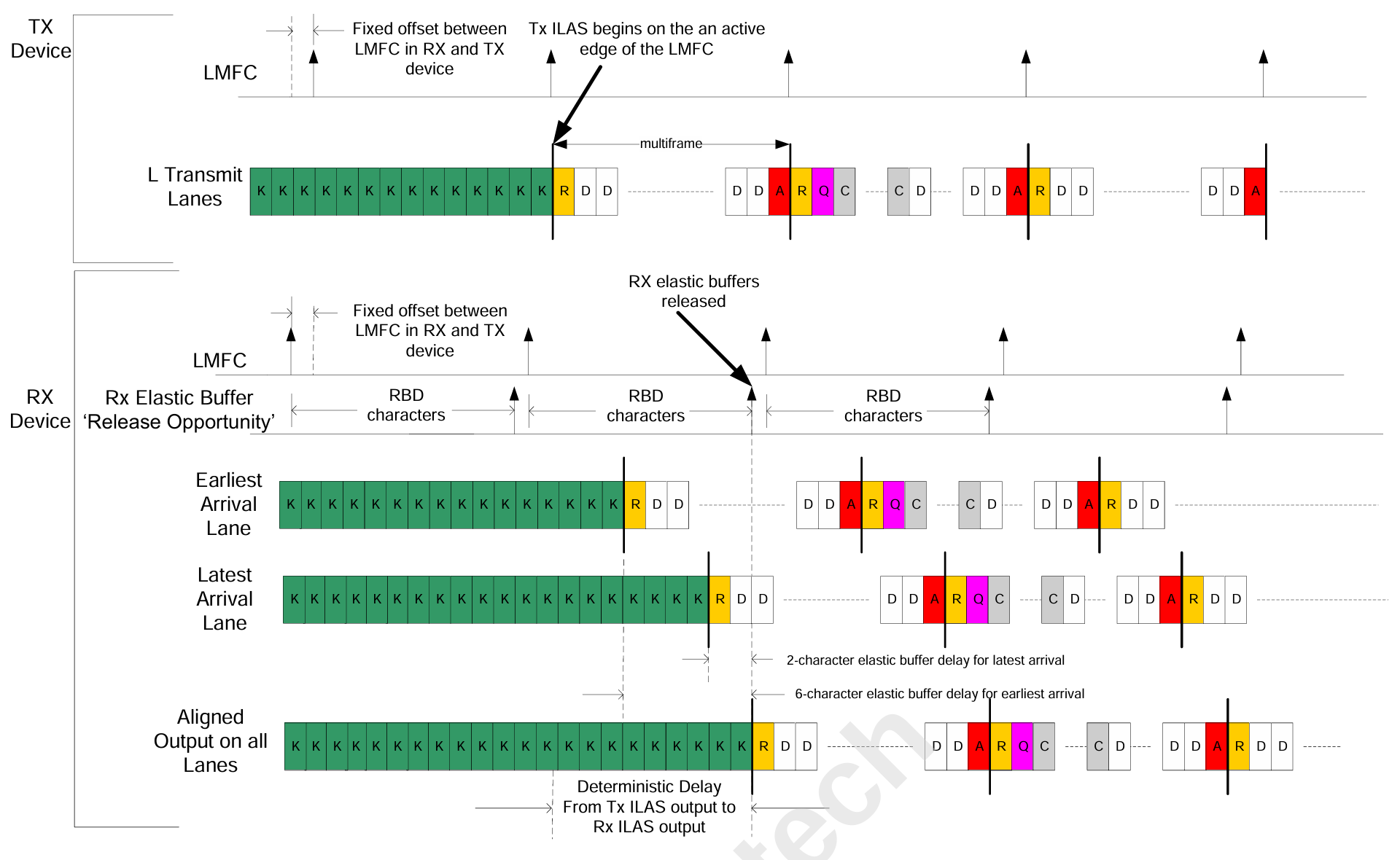
The selection of the RBD value should take into account margin for latency variations due to e.g., power reset or resynchronization of the link. The following might occur between two subsequent power-ups in the same system if this were not the case:
- The start of a multiframe or extended multiblock on the slowest lane arrives at the Rx just soon enough for a particular release opportunity. In this case the data is released from the buffer with little delay.
- The start of a multiframe or extended multiblock on the slowest lane arrives at the Rx just too late for a particular release opportunity. In this case the data is held for the next release opportunity and the buffer inserts close to a whole LMFC/LEMC period worth of delay.
Deterministic latency would not be preserved in the above example because the second instance would add exactly an LMFC/LEMC period worth of total link delay compared with the first instance.
4.2.2 No support for deterministic latency (device subclass 0 and device subclass 1 using MULTIREF)
In subclass 0 operation, the RX buffers are released at the earliest opportunity after the detection of a multiframe or extended multiblock boundary in each lane. Subclass 0 operation requires no alignment of LMFC/LEMCs across transmitter and receiver devices. Subclass 0 is intended for interfacing to JESD204A devices and for applications in which minimum link delay is desired, without need for deterministic latency.
In subclass 1 operation, the MULTIREF signal may be used to align the LMFC/LEMCs across converter devices (see 4.3.6). In this use case, the MULTIREF signal does not align the LMFC/LEMCs between the logic device and the converter devices. Therefore, this use case of the MULTIREF signal will not create deterministic latency. The MULTIREF signal replaces the lane-to-lane inter-device synchronization interface for subclass 0 DAC devices of the JESD204B standard as well as lane alignment across subclass 0 ADC devices using sync signal combination.
4.2.3 Deterministic latency using SYSREF (device subclass 1)
For subclass-1 devices, the creation of properly aligned LMFC/LEMC signals within TX and RX devices is achieved using a signal designated as 'SYSREF', which must be distributed to all converter and logic devices.
Delay uncertainty in the system is minimized by using highly accurate SYSREF / device clock signal pairs. While it is not mandatory, it is recommended that SYSREF be generated from the same device producing the TX and RX device clocks.
Due to the variety of allowable SYSREF signal types (periodic, one-shot (strobe-type), or "gapped" periodic), the variety of clock generator devices that may not support all the options for SYSREF generation, and to accommodate systems where SYSREF will be 'turned off' during normal operation, the following requirements for subclass-1 devices apply:
RX and TX logic Devices shall have the ability to issue a 'generate SYSREF' request, which enables the clock generator (or other SYSREF generating device) to generate one or more SYSREF pulses to all devices in the system or at least those connected to the link. All TX and RX devices shall have the ability to determine whether or not to adjust the phase alignment of their LMFC/LEMCs based on the next detected SYSREF pulse. Implementation details for this function are left to the device implementer but three possible options are listed below:
- Every SYSREF pulse may be examined by the device to determine if the existing phase alignment of the LMFC/LEMC requires adjustment.
- A device may be instructed via device input pin or control interface command to use the next detected SYSREF pulse to force a phase alignment of the LMFC/LEMC.
- A device may be instructed via device input pin or control interface command to ignore all future SYSREF pulses.
For subclass 1 devices, LMFC/LEMC phase re-alignment based on SYSREF will only be necessary in cases where a device is being initialized or where a link has exhibited a failure and wants to rule out LMFC/LEMC misalignment as a cause.
4.2.4 Deterministic latency using SYNC~ detection (device subclass 2)
Please refer to 8.5.