6.3 User data format for multiple lanes
For a link consisting of (L ) lanes, the same mapping method is used as for a single lane. However, in the last step, a row of (L · F ) octets is obtained. The first (F ) octets are transmitted over lane 0, the next (F) octets over lane 1, etc. The last (F ) octets are transmitted over lane (L - 1). This is illustrated in Figure 58.
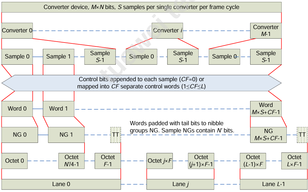
Compared to the independent lane format, the following additional specifications are needed:
-
Parameter HD controls whether a sample may be divided over more lanes. In the Low Density mode (HD = 0), partial conversion words at the end of a group of (F) octets are avoided by adding more tail bits (TT) after the last full nibble group (NG) in the group if necessary. In the High Density mode (HD = 1), the conversion words may break at the lane boundary.
-
Parameter CF, the total number of control words per frame period per link, controls which lanes will carry control words. (CF = 0) means that no control words are used. Other allowed (CF) values are common divisors of (L) and (M). The (L) lanes are divided into (CF) groups of (L / CF) lanes. Each group of lanes transmits the samples of (M / CF) converters. After these samples a control word is inserted, containing in successive order the control bits belonging to these samples. If the control word fits on a single lane, it is not allowed to break it over a lane boundary.
EXAMPLE: Mapping of a (16 \times (11 + 2))-bit converter with and without control words
Figure 59 shows the mapping of a (16 \times 11)-bit converter with two control bits per sample without using control words. Note that the control bits extend each 11-bit sample to a 13-bit word, which is further extended to four nibbles by means of tail bits. In total 32 octets must be transmitted during one frame period, e.g., using 8 lanes of 4 octets per frame.
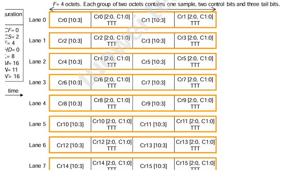
Figure 60 shows how the total amount of octets to transmit per frame period can be reduced to 28, by grouping all control bits into one control word, which is transmitted on the last lane. This way one lane can be saved. However, if only a fraction of the converters is active, there may be no saving in the amount of lanes that need to be powered on. For instance, to transmit only the data of converter 2, it is enough to activate lane 1 in the mapping of Figure 59, while lanes 0, 1 and 6 must be active in the mapping of Figure 60.
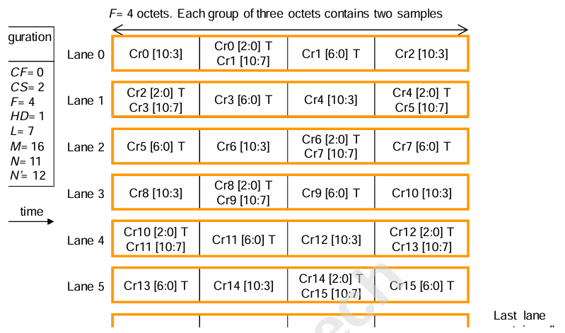
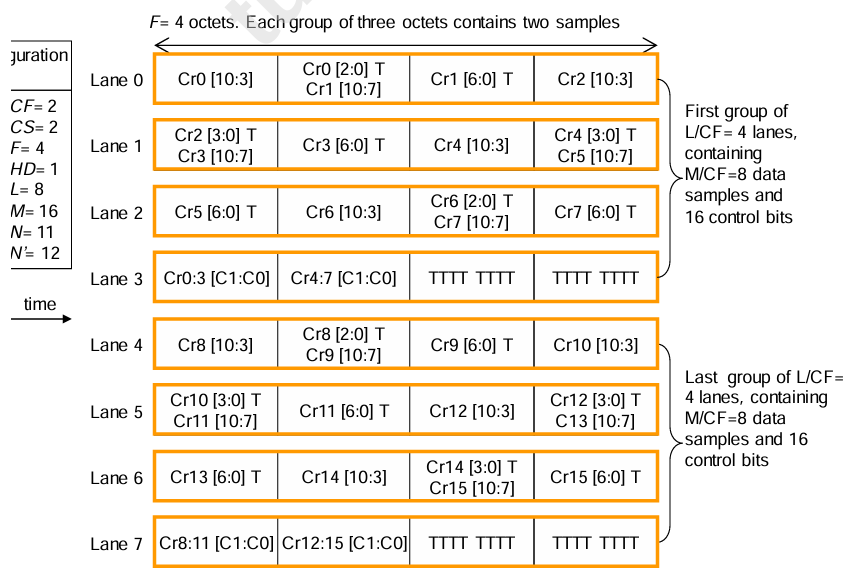
Figure 61 shows the mapping of the same converter when using two control words. No octets are saved in this configuration. There would be room for an extra sample to transmit on lane 3, but that is prohibited by the requirement to transmit the data of an equal amount of converters in each group.