Data and Command Interfaces
The transmitter and receiver cores incorporate AXI4-Stream interfaces for data ingress and egress. These AXI4-Stream interfaces include data and flow control signals only. In addition, there are supplementary control signals that are used to signal the timing of the data on the AXI4-Stream interface.
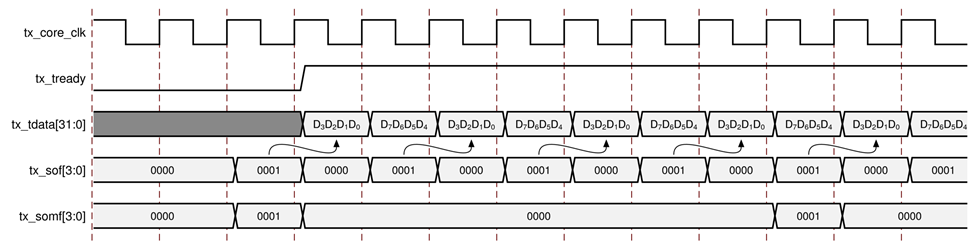
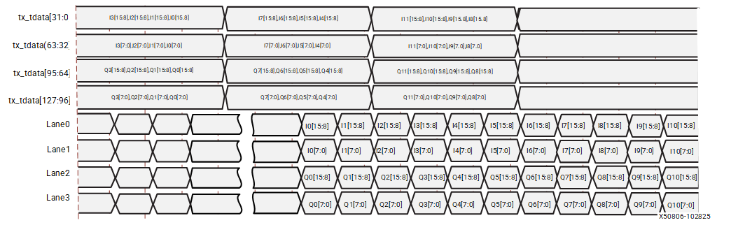
The AXI data input and output by the core contains 4-bytes per clock cycle per lane for 8B10B and 8-bytes per clock cycle per lane for 64B66B. The least significant byte position in each 32-bit or 64-bit block holds the first byte received from the ADC or transmitted to the DAC. The following figure shows an example of how AXI4-Stream data is mapped on to JESD204C using 8B10B encoding.
When you use the 64B66B encoding, the command interface operates in Multi-Lane mode. The JESD204C core uses the header ports of all available lanes to form the command channel.
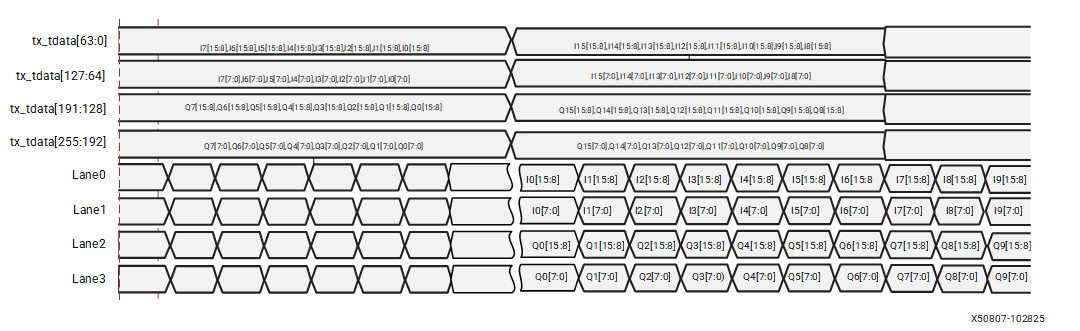
The following figure shows an example of how AXI4-Stream data is mapped on to JESD204C using 64B66B encoding.
The AXI4-Stream interfaces transfer the JESD204C transport layer- not raw converter samples. Refer to the appropriate converter data sheet for information on correctly mapping samples into the transport layer.
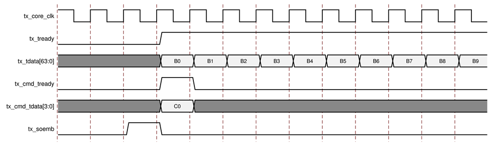
For a 64B66B transmitter, the following figure shows the timing of the tx_soemb (Start Of Extended Multiblock) signal relative to the AXI4-Stream data tx_tdata and tx_cmd_tdata. The tx_soemb signal is a single bit and it is set High in the cycle preceding the first data block of an extended multiblock. The data interface will transfer one 64-bit block B every core clock cycle. The command interface will transfer one command word (either 19-bit or 7-bit) every multiblock. If data is not available on the command interface (tx_cmd_tvalid = 1), then an IDLE command will be transmitted. The command interface has been padded out to 32 bits per lane. Only bits [18:0] or [6:0] are actually used, and all unused bits are set to 0.
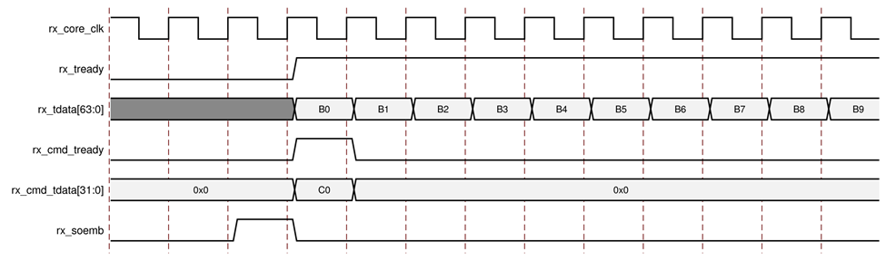
For a 64B66B receiver, the following figure shows the timing of the rx_soemb signal relative to the AXI4-Stream data rx_tdata. The rx_soemb signal is a single bit, and it is set High in the cycle preceding the first data block of an extended multiblock. The command interface will transfer one word every multiblock.