6 Design Notes
This section describes and illustrates the various design specific care-abouts of the TI204c JESD IP. Each sub-section is dedicated to a unique feature or aspect of the IP, and is intended to guide the designer through the steps and options for further customizing and optimizing the IP for the targeted application.
6.1 Transceiver Instantiation and Customization Guidelines
The following block diagram illustrates the instantiation of the Transceiver in the TI204c JESD IP core. The transceiver is embedded within the design and instantiated in a wrapper module with one of the following names:
- In the case of 8b/10b designs, the wrapper module is called "mgt_8b/10b_wrap". It instantiates the 8b/10b Transceiver IP.
- In the case of 64b/66b designs, the wrapper module is called "mgt_64b66b_wrap". It instantiates the 64b/66b Transceiver IP.
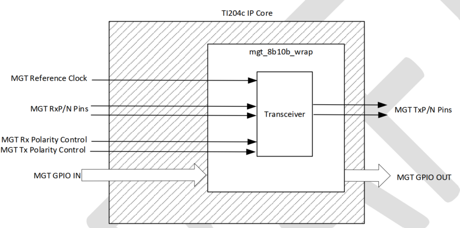
This is the only module in the JESD IP core that is not encrypted, and allows the designer the ability to customize the Transceiver IP for purposes that may be very specific to the application.
6.1.1 Transceiver Wrapper Module design guidelines
The transceiver wrapper module couples tightly with the control and data paths of the TI204c JESD IP core, and care should be taken to ensure that its instantiation within the IP core does not get affected by the customizations that are carried out. The following guidelines are essential for retaining proper functionality:
- The name of the wrapper (
mgt_xxxx_wrap) must be left unchanged. - The parameters of the module are directly inferred from the top level parameters of the JESD IP core, and must be left unchanged.
- The MGT GPIO in and out signals can be used by the designer for control/access to signals of the transceiver and for custom logic that is added to the transceiver wrapper. An example of this is adding DRP (configuration) ports to the transceiver IP, which can then be controlled/accessed from outside the JESD IP core through the GPIO ports.
The reference designs included in this user guide offer various Transceiver instantiation examples, and can be used as a starting point for further design development and customization.
6.2 Transceiver Reference Clock Setup and Data Pin Mapping Rules
The transceiver IP is generated using the Transceiver wizard tool in Vivado. This is a packaged IP that is instantiated inside the TI204c JESD IP, and hence it is important to ensure the correct mapping of reference clock and data pins of the FPGA to the appropriate pins of the ADC / DAC / clock buffers in the system. This section explains the various mapping nomenclature rules used by the Transceiver wizard for the final Transceiver IP that is generated.
6.2.1 Reference Design mapping example.
The following figure illustrates an 8 lane GTY transceiver example where the selected lanes are chosen from QuadX0Y0 and Quad X0Y1:
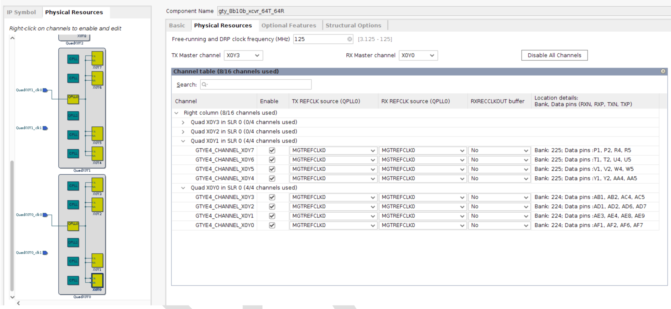
In the case above, the Vivado Transceiver Wizard will generate the transceiver IP (named gty_8b10b_xcvr_64T64R). The generated transceiver IP will order/name the lanes based on the channel numbering, and the same order will apply to the JESD IP ports:
- The 8 Rx and Tx lanes are part of the 8 channels in Quads X0Y0 and X0Y1
- The channel GTYE4_X0Y0 will be referenced as Lane 0
- The
mgt_lane_rxp/n[0]input port of the JESD IP will in turn be Lane 0 of the JESD Rx IP. This will map to FPGA pins AF2 and AF1 respectively - The
mgt_lane_txp/n[0]output port of the JESD IP will in turn be Lane 0 of the JESD Tx IP. This will map to FPGA pins AF7 and AF6 respectively
- The
- The channel GTYE4_X0Y1 will be referenced as Lane 1
- The
mgt_lane_rxp/n[1]input port of the JESD IP will in turn be Lane 1 of the JESD Rx IP. This will map to FPGA pins AE4 and AE3 respectively - The
mgt_lane_txp/n[1]output port of the JESD IP will in turn be Lane 1 of the JESD Tx IP. This will map to FPGA pins AE9 and AE8 respectively
- The
- And so on... until
- The channel GTYE4_X0Y7 will be referenced as Lane 7
- The
mgt_lane_rxp/n[7]input port of the JESD IP will in turn be Lane 7 of the JESD Rx IP. This will map to FPGA pins P2 and P1 respectively - The
mgt_lane_txp/n[7]output port of the JESD IP will in turn be Lane 7 of the JESD Tx IP. This will map to FPGA pins R5 and R4 respectively
- The
Each Quad's QPLL0 will receive its input from the respective Quad's MGTREFCLK0 input pin.
Important: Note that the name used for the transceiver IP is just an example. It can be modified, as long as the same instance name is used in the mgt_xxxx_wrap module.
6.2.2 Modified mapping example
The following figure illustrates an 8T/8R transceiver. This time, the 8 lanes chosen are split across 3 Quads (and not contiguous).
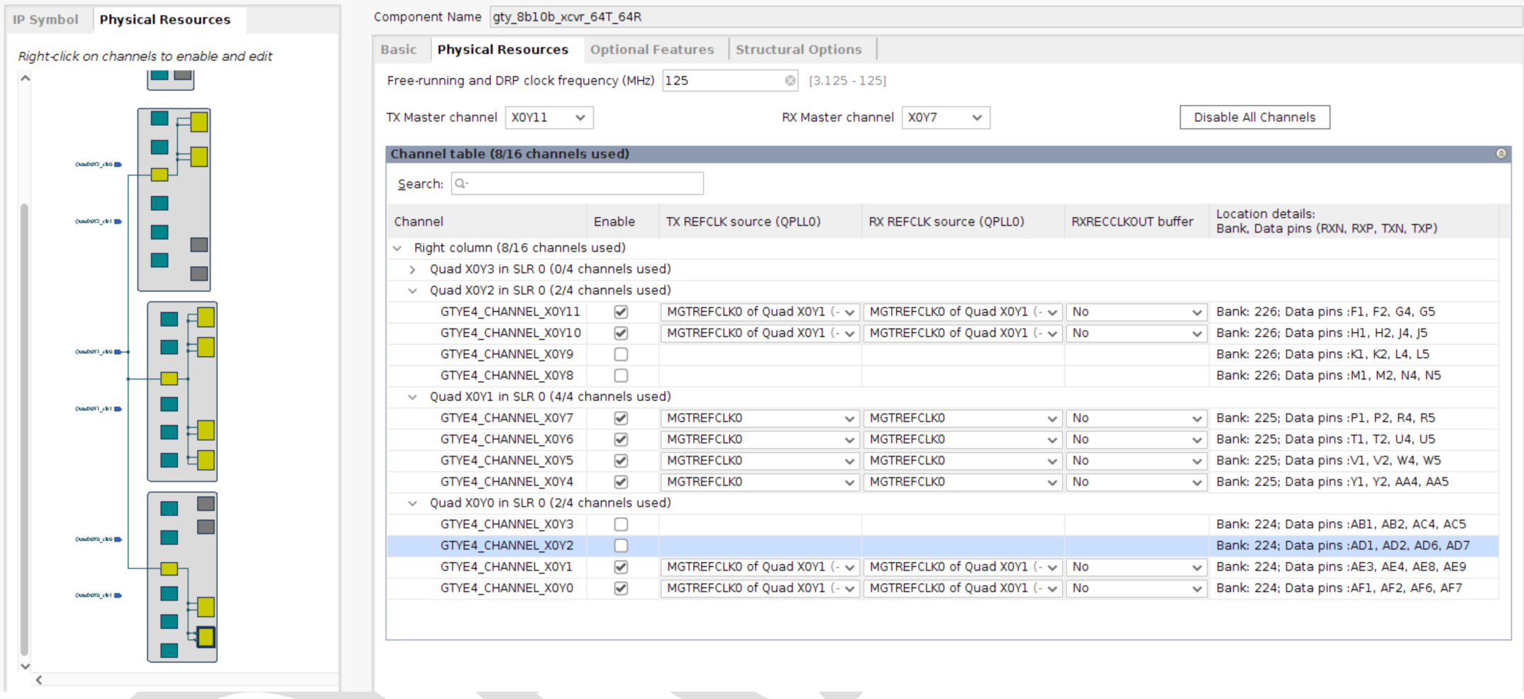
In the modified case, the generated transceiver IP will order/name the lanes based on the channel order from low to high. It is extremely important to note this, in order to ensure the correct mapping of the transceiver IP lanes to the top level ports of the TI204c JESD IP.
-
The 8 Rx and Tx lanes are selected from Quads X0Y0, X0Y1 and X0Y2
-
The channel GTYE4_X0Y0 will be referenced as Lane 0
- The
mgt_lane_rxp/n[0]input port of the JESD IP will in turn be Lane 0 of the JESD Rx IP. This will map to FPGA pins AF2 and AF1 respectively - The
mgt_lane_txp/n[0]output port of the JESD IP will in turn be Lane 0 of the JESD Tx IP. This will map to FPGA pins AF7 and AF6 respectively
- The
-
The channel GTYE4_X0Y1 will be referenced as Lane 1
- The
mgt_lane_rxp/n[1]input port of the JESD IP will in turn be Lane 1 of the JESD Rx IP. This will map to FPGA pins AE4 and AE3 respectively - The
mgt_lane_txp/n[1]output port of the JESD IP will in turn be Lane 1 of the JESD Tx IP. This will map to FPGA pins AE9 and AE8 respectively
- The
-
The channel GTYE4_X0Y4 will be referenced as Lane 2
- The
mgt_lane_rxp/n[2]input port of the JESD IP will in turn be Lane 2 of the JESD Rx IP. This will map to FPGA pins Y2 and Y1 respectively - The
mgt_lane_txp/n[2]output port of the JESD IP will in turn be Lane 2 of the JESD Tx IP. This will map to FPGA pins AA5 and AA4 respectively
- The
-
And so on... until
-
The channel GTYE4_X0Y11 will be referenced as Lane 7
- The
mgt_lane_rxp/n[7]input port of the JESD IP will in turn be Lane 7 of the JESD Rx IP. This will map to FPGA pins F2 and F1 respectively - The
mgt_lane_txp/n[7]output port of the JESD IP will in turn be Lane 7 of the JESD Tx IP. This will map to FPGA pins G5 and G4 respectively
- The
-
There is only one MGTREFCLK0 pin used in the FPGA, and that is the REFCLK0 pin of QuadX0Y1
- This clock buffer is connected to the QPLL0 of QuadX0Y1 and also feeds north and south to feed the QPLL0's of QuadX0Y2 and QuadX0Y0 respectively
- The transceiver IP generated by the transceiver Wizard will still define a 3 port reference clock input, but the GTYE4_IBUFDS clock buffer is expected to be connected to all three ports in the transceiver wrapper file.
6.3 Pin Mapping guidelines between the ADC/DAC and the JESD IP (FPGA)
The TI204c JESD IP offers integrated features to address both mapping and polarity related irregularities. All the data lanes of an ADC/DAC may not be connected to the respective counterpart lanes of the Rx/Tx lanes of the FPGA (JESD IP) in the correct order or polarity. Due to board design and routing challenges, it is often possible that one (or both) of the following occur on some of the lanes:
- The lanes aren't a direct 1-1 map between the FPGA and the data converter. For example, Lane 0 of the ADC is not routed to Rx Lane 0 of the JESD IP (on the FPGA). Instead, Lane 0 of the ADC is connected to Lane 4 of the Rx IP. Similarly, Lane 2 of a DAC may be routed to Lane 5 of the Tx IP on the FPGA.
- a. Such mapping irregularities can make the final FPGA design challenging, because it can be difficult to accurately map the data transmitted / received on lanes to the respective converter sample values.
- There may be polarity inversions between the transmitter and the receiver. For example, the TxP output pin of a certain lane of the transmitter (i.e. the FPGA's Tx IP) is connected to the RxN input pin of the receiver lane of the DAC.
- a. Polarity inversions will typically cause lane initialization to fail in 64b/66b modes. However, in 8b/10b mode, the encoding protocol may mask the inversion by allowing the link to get established, but the sample values will be corrupted.
6.3.1 Pin mapping for ADC connected to an Rx IP
The following image illustrates an 8 lane ADC connected to an 8 lane Rx IP in the FPGA. The symbol  illustrates a polarity inversion.
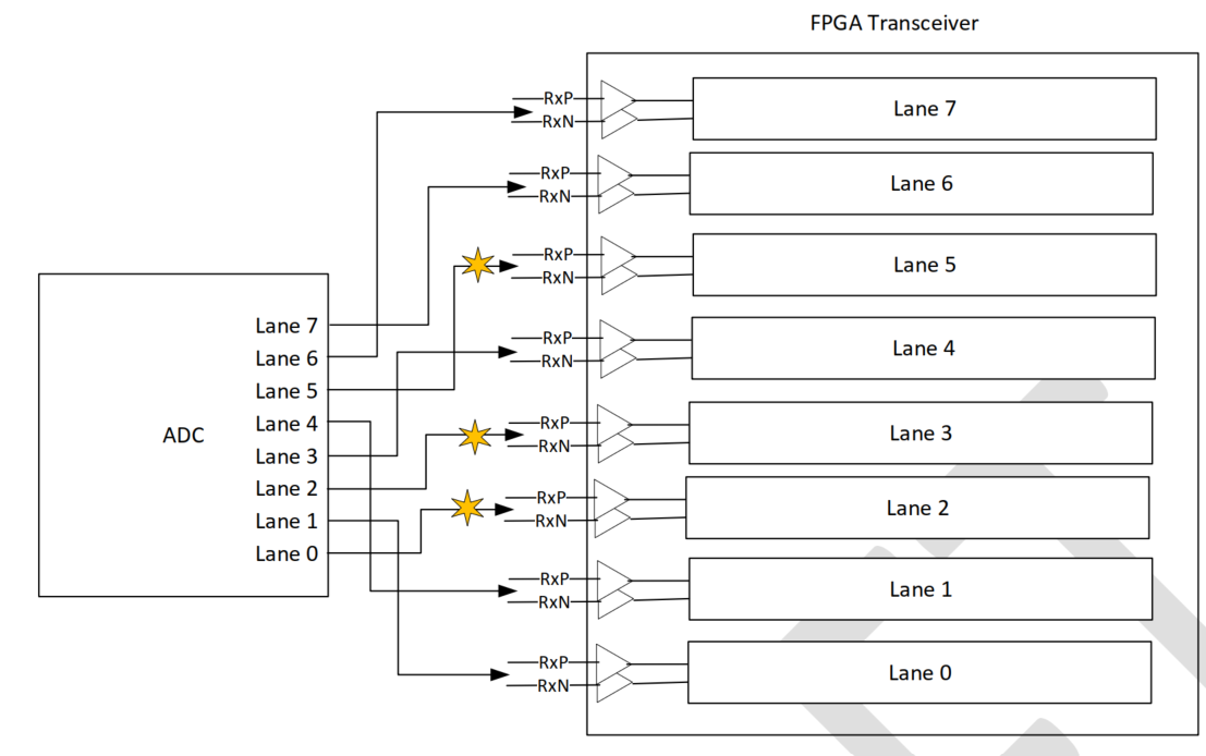
The mapping is represented in the following table:
| ADC Lane Number | FPGA Rx IP Lane Number | Inversion (Y/N) |
|---|---|---|
| 0 | 2 | Y |
| 1 | 0 | N |
| 2 | 3 | Y |
| 3 | 4 | N |
| 4 | 1 | N |
| 5 | 5 | Y |
| 6 | 7 | N |
| 7 | 6 | N |
The above mapping will result in the following port values for the JESD IP:
cfg_rx_lane_map = {3'd6, 3'd7, 3'd5, 3'd1, 3'd4, 3'd3, 3'd0, 3'd2}
cfg_rx_lane_polarity = 8'b00100101
Note: The values should be based on the perspective of the lanes of the ADC (ordered from highest to lowest).
6.3.2 Pin mapping for DAC connected to a Tx IP
The following image illustrates an 8 lane DAC connected to an 8 lane Tx IP in the FPGA. The symbol illustrates a polarity inversion.
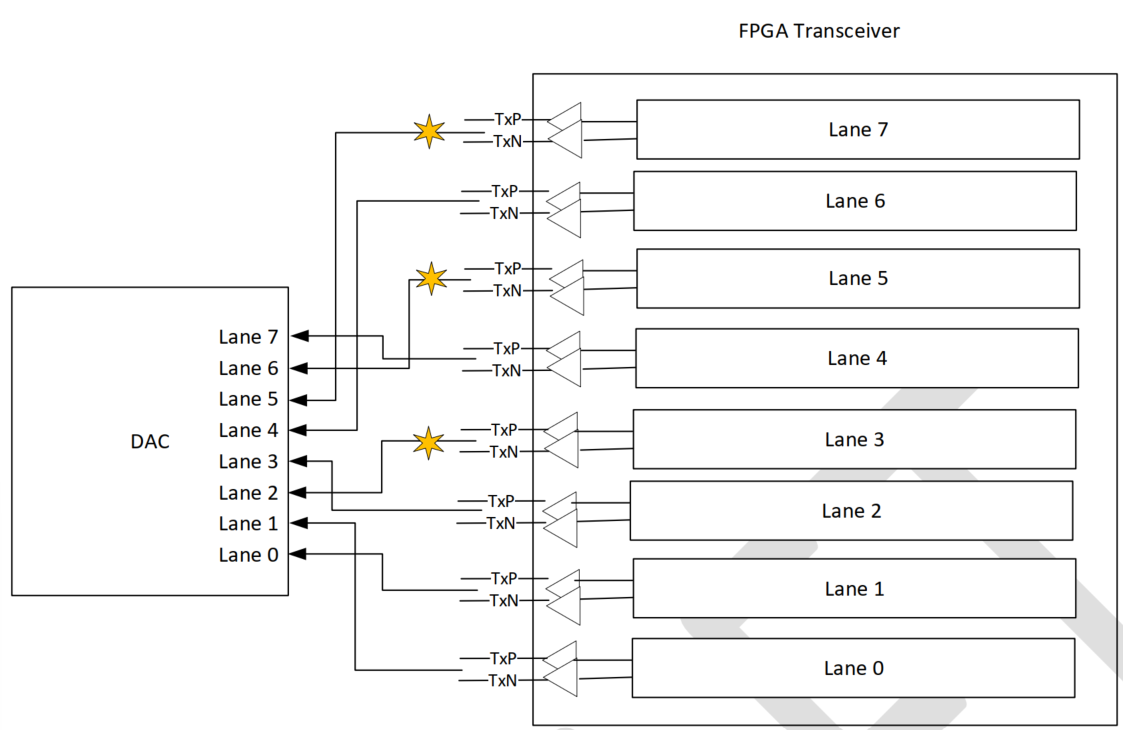
The mapping is represented in the following table:
| DAC Lane Number | FPGA Tx IP Lane Number | Inversion (Y/N) |
|---|---|---|
| 0 | 1 | N |
| 1 | 0 | N |
| 2 | 3 | Y |
| 3 | 2 | N |
| 4 | 6 | N |
| 5 | 7 | Y |
| 6 | 5 | Y |
| 7 | 4 | N |
The above mapping will result in the following port values for the JESD IP:
cfg_tx_lane_map = {3'd4, 3'd5, 3'd7, 3'd6, 3'd2, 3'd3, 3'd0, 3'd1}
cfg_tx_lane_polarity = 8'b01100100
Note: The values should be based on the perspective of the lanes of the DAC (ordered from highest to lowest).
6.4 IP Clock guidelines
The JESD IP contains the following clock related inputs and outputs:
6.4.1 MGT Free-running Clock
The transceiver IP requires a free-running clock for basic initialization and reset control. This is usually a low frequency clock and does not have strict jitter requirements, and can hence be provided from any clock source available in the FPGA. However, it is important that the clock is stable before the master reset of the JESD IP is released.
The frequency of this clock can be chosen in the transceiver wizard. An example is the 125MHz setting illustrated in Mapping of Selected Transceiver Channels. The allowed range of the clock is also listed in the same parameter window of the Transceiver Wizard.
6.4.2 MGT Reference Clock (input)
This is the set of inputs that drive the reference clock to the MGT transceiver clocking resources (QPLLs / CPLLs). These must be connected to the MGTREFCLK pins of the FPGA. The following figure illustrates the typical topology of clocks within a Quad (4 channel group). Note that this figure applies to the GTH and GTY class transceivers. The GTX and GTP class may have a different architecture.
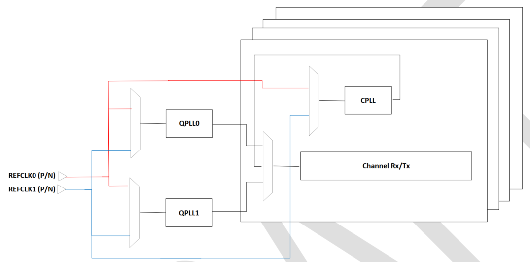
As illustrated in Figure 1: Typical Clocking Topology for a Quad the final clock used for data extraction can be selected from the QPLL0 or QPLL1 or the CPLL. Each PLL has a range of operation, and the designer must refer to the guidelines in the respective datasheet of the FPGA and the transceiver User Guide.
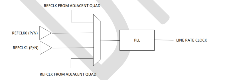
Furthermore, the PLLs may receive their reference clock either directly from the REFCLK pins of the same Quad or from adjacent Quads. This is illustrated in Figure 2: Reference clock options for the QPLL0/QPLL1/CPLL.
6.4.3 MGT generated Rx IP clock (output) :
This is the clock generated by the Rx channels in the transceiver, and can be used to drive logic in the FPGA fabric. This is internally driven by a BUFG and does not require any additional clock buffer instantiations outside the JESD IP.
6.4.4 MGT generated Tx IP clock (output):
This is the clock (mgt_tx_usrclk2) generated by the Tx channels in the transceiver, and can be used to drive logic in the FPGA fabric. The frequency of this clock is derived from the Line Rate and is described in the table below:
| Encoding protocol | TX_LN_DATA_WIDTH | Frequency |
|---|---|---|
| 8b/10b | 32 | LineRate/40 |
| 8b/10b | 64 | LineRate/80 |
| 64b/66b | 32 | LineRate/33 |
| 64b/66b | 64 | LineRate/66 |
| 64b/66b | 128 | LineRate/132 |
Note: The mgt_tx_usrclk2 is internally driven by a BUFG and does not require any additional clock buffer instantiation outside the JESD IP.
6.4.5 MGT generated Rx IP clock (output):
This is the clock (mgt_rx_usrclk2) generated by the Rx channels in the transceiver, and can be used to drive logic in the FPGA fabric. The frequency of this clock is derived from the Line Rate and is described in the table below:
| Encoding protocol | RX_LN_DATA_WIDTH | Frequency |
|---|---|---|
| 8b/10b | 32 | LineRate/40 |
| 8b/10b | 64 | LineRate/80 |
| 64b/66b | 32 | LineRate/33 |
| 64b/66b | 64 | LineRate/66 |
| 64b/66b | 128 | LineRate/132 |
Note: The mgt_rx_usrclk2 is internally driven by a BUFG and does not require any additional clock buffer instantiation outside the JESD IP.
6.4.6 Tx IP System Clock (tx_sys_clock)
The tx_sys_clock drives the blue domain illustrated in the Tx IP block diagrams in the TI204c-IP High Level Block Diagram section of this user guide. This is the primary domain used for interaction between the JESD Tx IP and the upstream application logic.
The tx_sys_clock frequency is fixed based on the IP configuration and is described below:
| Encoding protocol | TX_LN_DATA_WIDTH | Frequency |
|---|---|---|
| 8b/10b | 32 | LineRate/40 |
| 8b/10b | 64 | LineRate/80 |
| 64b/66b | 32 | LineRate/33 |
| 64b/66b | 64 | LineRate/66 |
| 64b/66b | 128 | LineRate/132 |
Notes:
- The
tx_sys_clockcan be driven by themgt_tx_usrclk2output of the JESD IP, as the frequencies are exactly identical. However, this is encouraged only for designs that do not need deterministic latency, which involves accurate sampling of the SYSREF input pin for synchronizing timing between the transceiver and receiver. - If deterministic latency is required, the
tx_sys_clockshould be sourced independently through a dedicated clock capable input pin of the FPGA, which will allow tight control of its timing with respect to the SYSREF pin. If thetx_sys_clockis sourced independently, it should still be generated from a common root clock being used to generate DAC as well as the MGTREFx clocks. This will ensure that any drift in the clock impacts all the components together.
6.4.7 Rx IP System Clock (rx_sys_clock)
The rx_sys_clock drives the blue domain illustrated in the various figures in the Rx IP block diagrams of the TI204c-IP High Level Block Diagram section of this user guide. This is the primary domain used for interaction between the JESD Rx IP and the downstream application logic.
The rx_sys_clock frequency has a lower limit based on the IP configuration and is described below:
| Encoding protocol | RX_LN_DATA_WIDTH | Frequency (should be equal to or greater than the following) |
|---|---|---|
| 8b/10b | 32 | LineRate/40 |
| 8b/10b | 64 | LineRate/80 |
| 64b/66b | 32 | LineRate/33 |
| 64b/66b | 64 | LineRate/66 |
| 64b/66b | 128 | LineRate/132 |
Notes:
- The
rx_sys_clockcan be driven by themgt_rx_usrclk2output of the JESD IP, as the frequencies are exactly identical. However, this is encouraged only for designs that do not need deterministic latency, which involves accurate sampling of the SYSREF input pin for synchronizing timing between the transceiver and receiver. - If deterministic latency is required, the
rx_sys_clockshould be sourced independently through a dedicated clock capable input pin of the FPGA, which will allow tight control of its timing with respect to the SYSREF pin. If therx_sys_clockis sourced independently, there are two options:- If the frequency is exactly at the lower limit as per the table above, it should still be generated from a common root clock being used to generate ADC as well as the MGTREFx clocks. This will ensure that any drift in the clock impacts all the components together.
- If the frequency is greater than the lower limit as per the table above, it can be generated using any clock source available in the FPGA. In this case, the IP will de-activate the
rx_data_validsignal and hold the data on all the lanes whenever one or more lanes have an empty buffer.
6.5 Mapping of Rx/Tx lane data to ADC/DAC samples
The TI204c JESD IP has been architected to enable an easy and straightforward mapping of the data-converter samples to the respective data ports of the Rx and Tx IPs. This is carried out by implementing a 1-1 correlation between the JMODE/LMFS table of the data-converter and the rx_lane_data and tx_lane_data ports of the JESD IP. This, in turn, enables an easy sorting of ADC samples for downstream data processing or easy mapping of upstream samples to the Tx IP for transmission to the DAC.
6.5.1 Mapping of Rx Lane Data to ADC samples
The following figure illustrates the JMODE0 and JMODE30 output format of the ADC12DJ5200RF ADC. JMODE0 is an 8b/10b protocol, while JMODE30 is a 64b/66b protocol. In both cases the ADC generates 12 bit samples that are packed into the 8 lanes as shown in the table below. The important points to note are:
- The table defines a 64 bit frame (per lane)
- Each lane has 4 tail bits after every 60 bits (5 samples per 64 bit packet)
- 8 lanes create a total of 40 samples in each frame
- The samples are arranged from S0 to S39, with S0 appearing on Lane 0, S1 on Lane 4, S2 on Lane 2 and so on
Table 27. JMODE 0 (12-bit, Single Channel, DDC Bypass, 8 lanes)
| OCTET | 0 | 1 | 2 | 3 | 4 | 5 | 6 | 7 | ||||||||
|---|---|---|---|---|---|---|---|---|---|---|---|---|---|---|---|---|
| NIB | 0 | 1 | 2 | 3 | 4 | 5 | 6 | 7 | 8 | 9 | 10 | 11 | 12 | 13 | 14 | 15 |
| DA0 | S[0] | S[8] | S[16] | S[24] | S[32] | T | ||||||||||
| DA1 | S[2] | S[10] | S[18] | S[26] | S[34] | T | ||||||||||
| DA2 | S[4] | S[12] | S[20] | S[28] | S[36] | T | ||||||||||
| DA3 | S[6] | S[14] | S[22] | S[30] | S[38] | T | ||||||||||
| DB0 | S[1] | S[9] | S[17] | S[25] | S[33] | T | ||||||||||
| DB1 | S[3] | S[11] | S[19] | S[27] | S[35] | T | ||||||||||
| DB2 | S[5] | S[13] | S[21] | S[29] | S[37] | T | ||||||||||
| DB3 | S[7] | S[15] | S[23] | S[31] | S[39] | T | ||||||||||
Table 27 also applies to JMODE 30.
The waveforms below illustrate the data output by the Rx IP when connected to the ADC (configured to JMODE0). For the purpose of clarity, the waveform shows a total of 120 samples, A0 through A39, B0 through B39 and C0 through C39.
6.5.1.1 Data mapping with 64 bit Rx IP
The following waveform is the rx_lane_data output of the Rx IP (with RX_LN_DATA_WIDTH set to 64).
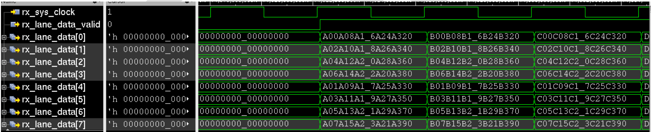
The transition of rx_lane_data_valid indicates the start of data from the Rx IP, showing that all the lanes release in an aligned manner.
The reader should be able to see a direct 1-1 correlation between the sample ordering on the rx_lane_data buses and the JMODE table. On each lane, each 64 bit packet has 4 tail bits of 'h0 at the LSB nibble.
6.5.1.2 Data mapping with 32 bit Rx IP
The following waveform is the rx_lane_data output of the Rx IP (with RX_LN_DATA_WIDTH set to 32).
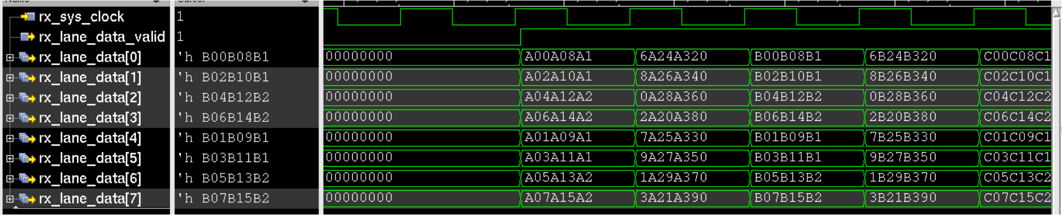
The transition of rx_lane_data_valid indicates the start of data from the Rx IP, showing that all the lanes release in an aligned manner. The reader should still be able to see a direct 1-1 correlation between the sample ordering on the rx_lane_data buses and the JMODE table. On each Lane, the 64 bit packet is now received in two consecutive cycles of 32 bit each. The 4 tail bits still occur after every 60 bits.
6.5.1.3 Data mapping with 128 bit Rx IP
The following waveform is the rx_lane_data output of the Rx IP (with RX_LN_DATA_WIDTH set to 128).
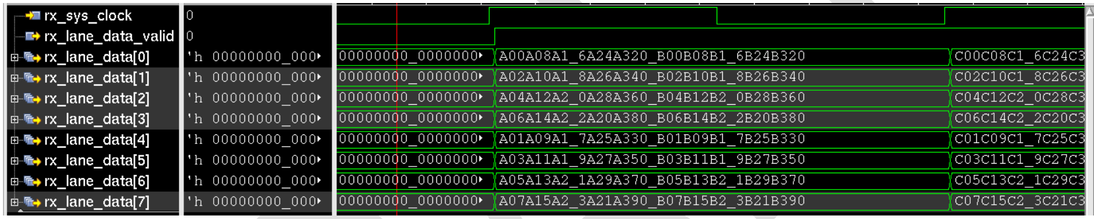
The transition of rx_lane_data_valid indicates the start of data from the Rx IP, showing that all the lanes release in an aligned manner. The reader should still be able to see a direct 1-1 correlation between the sample ordering on the rx_lane_data buses and the JMODE table. On each Lane, two 64 bit packets are received in each rx_sys_clock cycle. The 4 tail bits still occur after every 60 bits.
6.5.2 Mapping of DAC samples to Tx Lane Data
The following figure illustrates the LMFS = 8411 input format of the DAC38J84 data converter. The DAC is a two channel device with 16 bit samples that are packed into the 8 lanes as shown in the table. The important points to note are:
- Each sample is split across 2 lanes.
- Lanes 0-3 map the I channel, while Lanes 4-7 map the Q channel
Table 10. JESD204B Frame Assembly Byte Representation (Dual-Channel)
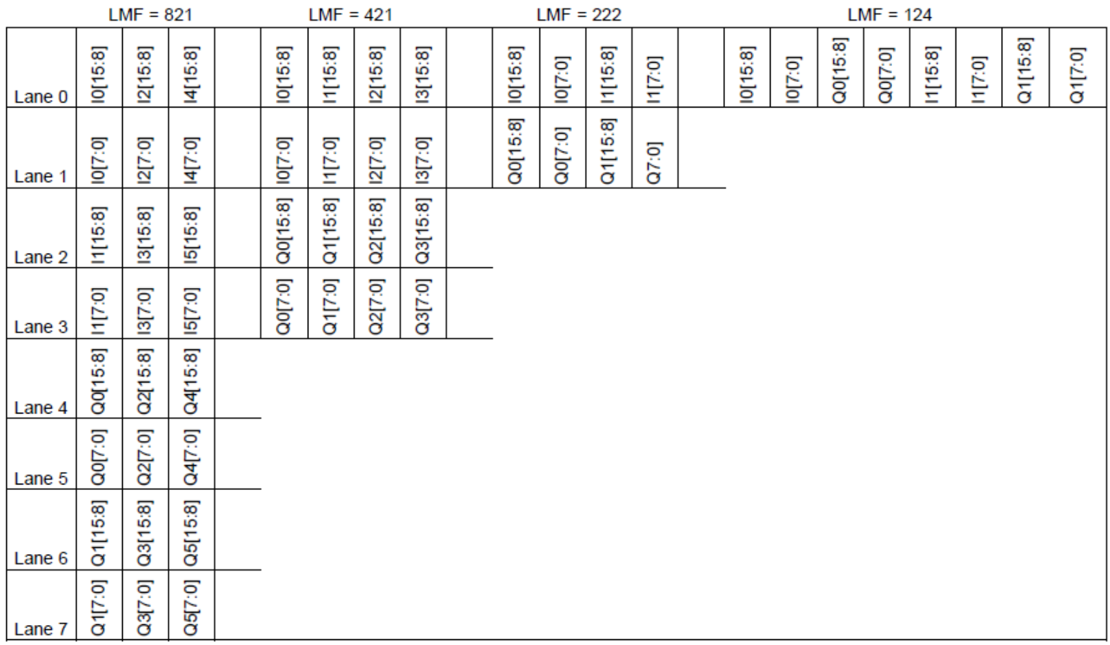
The waveforms below illustrate the data input to the Tx IP when connected to the DAC (configured to LMFS = 8411). For the purpose of clarity, the waveform shows a total of 48 samples on each channel. The I channel samples are AB00 through AB47, while the Q channel samples are CD00 through CD47.
6.5.2.1 Data mapping with 64 bit Tx IP
The following waveform is the tx_lane_data input to the Tx IP (with TX_LN_DATA_WIDTH set to 64).
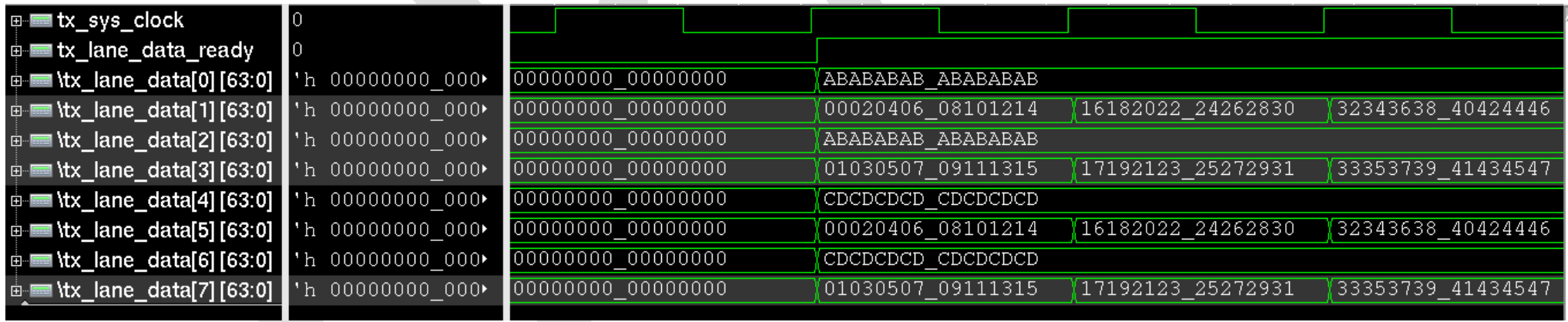
- The transition of
tx_lane_data_readyindicates the Tx IP is ready to start accepting data on all the lanes. - The reader should be able to see a direct 1-1 correlation between the sample ordering on the
tx_lane_databuses and the LMFS table. Each sample is divided among two onsecutive lanes, with the lower numbered lane containing the 8 MSB bits and the higher numbered lane containing the 8 LSB bits.
6.5.2.2 Data mapping with 32 bit and 128 bit Tx IP
The waveforms for the 32bit and 128 bit Tx IPs are not shown, but the sample to lane data mapping remains the same.
- In the 32 bit Tx IP case, the IP will accept 8 samples each of the I and Q channels on each tx_sys_clock cycle
- This is because there are 8 lanes of 32 bits each, resulting in a total of 16 total samples per cycle
- In the 128 bit Tx IP case, the IP will accept 32 samples each of the I and Q channels on each tx_sys_clock cycle
- This is because there are 8 lanes of 128 bits each, resulting in a total of 64 total samples per cycle
6.6 Guidelines for accurate sampling of SYSREF
The SYSREF signal is an integral component of a JESD system, and is used to help synchronize the internal timing of the various Tx and Rx devices in the case of JESD Subclass 1 deterministic latency. Each device is supplied a SYSREF signal and a clock, and the SYSREF is sampled for a positive edge using the provided clock.
The SYSREF signal can have the following characteristics:
- It can be one‑shot or periodic or gapped periodic.
- The period of the SYSREF must be equal to or an integral multiple of the following:
- The period of the multi‑frame in 8b/10b mode
- The period of the extended multi‑block in 64b/66b mode
The TI204c IP has features that enable accurate sampling of SYSREF without specific duty cycle constraints being imposed on the SYSREF signal.
-
The pulse width of the SYSREF should last for at least one clock cycle. Wider pulses do not change the functionality, because the positive edge of the clock that samples the
0→1transition of the SYSREF is the event used to control the LEMC/LMFC timing in the IP. -
In some cases, tight timing constraints may force the addition of one or more sequential stages between the SYSREF at the input pin of the FPGA and the final SYSREF that is passed to the JESD IP. The IP has a feature that can compensate for the offset created by these stages. This is done using the
RX_SYSREF_OFFSETandTX_SYSREF_OFFSETattributes of the IP. -
The IP also exports a counter that tracks the number of times that the SYSREF pulse has forced a re‑alignment of the LEMC/LMFC timing. This can be used to track cases where the SYSREF frequency is not an integral multiple of the extended multi‑block or multi‑frame period.
The following waveform illustrates a case where the RX_SYSREF_OFFSET is set to 1. The Rx IP has just been released from reset, and its LEMC pulse is out of sync with the Tx LEMC pulse (seen at the TimeA marker in the waveform). The rx_lemc_pulse and tx_lemc_pulse have been highlighted in red for easy reference.
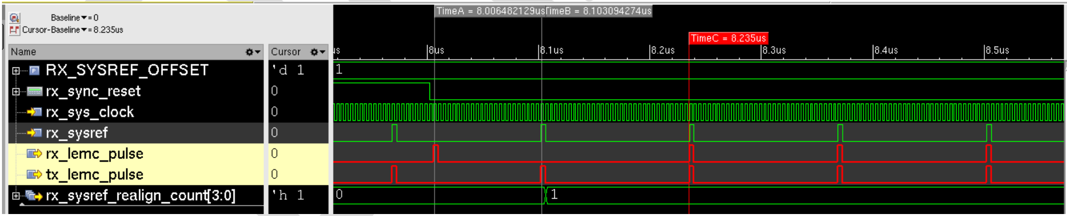
At the point of the second marker (TimeB), the Rx IP re‑aligns its internal timing, and the realign counter increments from 0x0 to 0x1. Starting from the third marker (TimeC) the Rx and Tx LEMC pulses are aligned, indicating that the Tx and Rx IPs are honoring the extended multi‑block timing of the JESD link. After this point, the rx_sysref_realign_count does not increment again, indicating that the timing of the rx_sysref is in accordance with the timing of the rx_lemc_pulse.
In cases where deterministic latency or synchronization across multiple IPs is not required, the rx_sysref and tx_sysref inputs to the IP can be tied to 0.
6.7 Synchronizing multiple Rx IPs for simultaneous release of lanes
The TI204c IP supports synchronized release across multiple instances of its Rx IP. This is done by monitoring an output signal called "rx_all_lanes_locked", and in turn using it to control the release of the Rx IP's data lanes. The "rx_all_lanes_locked" signal indicates that each individual lane in the IP has aligned to the relevant control / demarcation characters sent by the corresponding Tx / ADC device. This signal is applicable in both 8b/10b as well as 64b/66b modes of operation. However, with multiple Rx IP's in the system, it is possible that each Rx IP completes its locking procedure during a different multiframe or extended multi-block. This can create scenarios where Rx IP's release at different points in time, even though their LEMC/LMFC boundaries are synchronized by using the SYSREF signal.
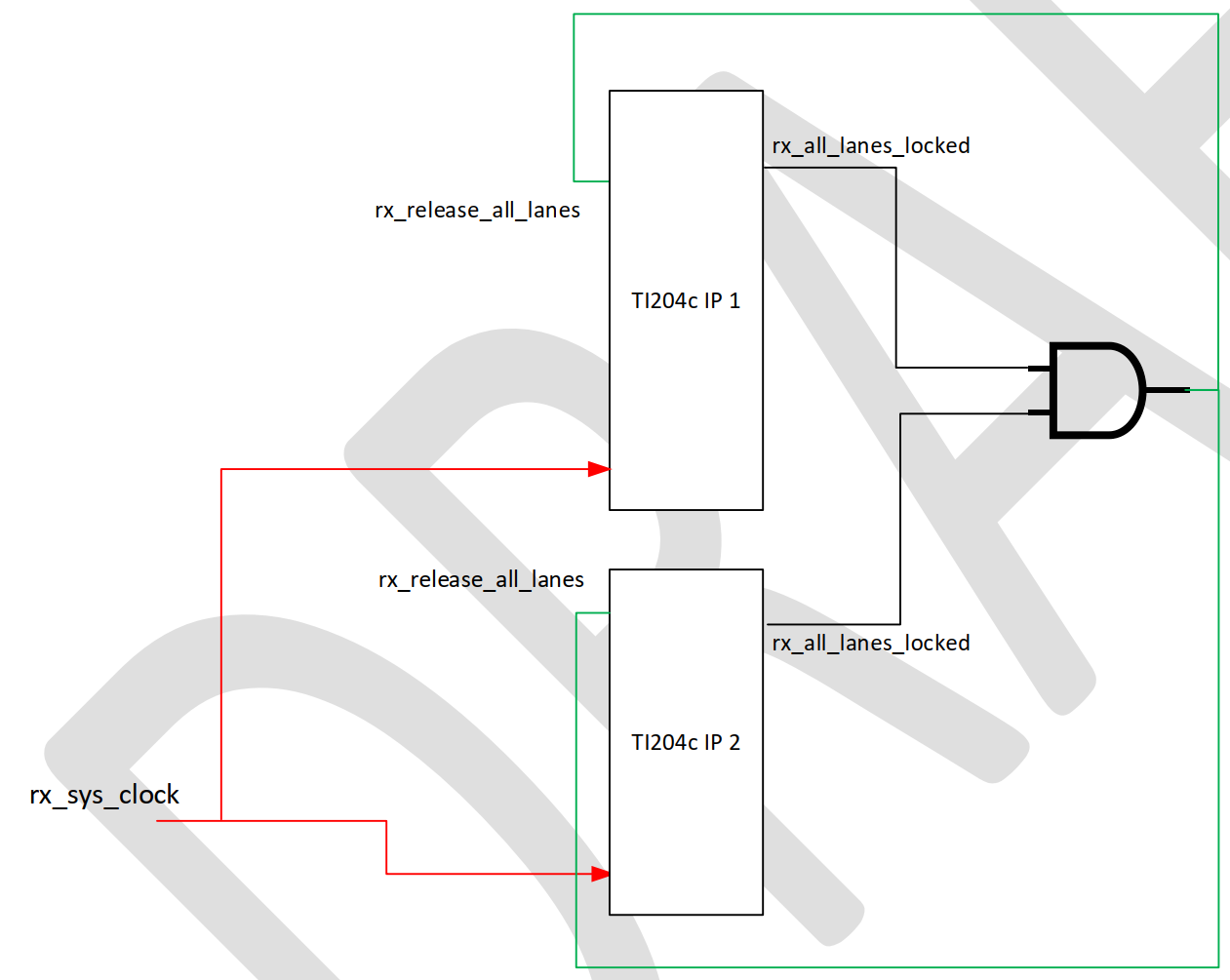
If there are multiple IP's in a system, the following topology can be used to ensure that all IP's are released simultaneously, even if the lanes in each IP complete their locking at different points in time. This helps simultaneous sampling systems ensure that the data from all channels across multiple devices is aligned in time.
The figure below indicates that all lock status and release control signals are synchronous to the rx_sys_clock clock domain. All lanes of each IP will be released on the next LEMC/LMFC boundary after the input "rx_release_all_lanes" signal has been set to '1' (and the IP has completed locking for all of its lanes).
-
For the above scheme to work reliably, it is important to ensure that all the IP's have aligned to their individual SYSREF signals, which in turn ensures that the IP's are aligned in terms of their multi-frame or extended multiblock boundaries.
-
If there is just one Rx IP in the system, its input "
rx_release_all_lanes" port can be tied to '1'. Alternatively, itsrx_all_lanes_lockedoutput port can be connected back to the "rx_release_all_lanes" input port. -
The
rx_sys_clocksignal (in RED) is shown only for the purpose of illustrating that the "rx_all_lanes_locked" and "rx_release_all_lanes" signals use therx_sys_clockdomain.
- The scheme described above ensures that multiple Rx IP’s release within the same Multi-Frame or Extended Multi-Block boundary. However, while the lanes within an IP will always release together, there may be a variation of +/-1 rx_sys_clock cycles between the data of lanes across the IPs. This is because there may be delay variations across the IPs which result in the samples shifting forward (or back) by 1 rx_sys_clock cycle.
- This variation will not cause system level issues in cases where samples are tracked in the time domain
- For example, if sample 1 of Rx IP 1 has a -1/0/+1 rx_sys_clock relationship to sample 1 of Rx IP 2, this relationship will be maintained across all subsequent samples (until the next time the link is reinitialized).
- However, if it is desired that corresponding samples on all lanes of all Rx IP’s must be aligned to the exact rx_sys_clock cycle, then the scheme described above must be combined with the deterministic latency feature of the TI204c IP (discussed in the next sub-section).
6.8 Implementing Deterministic Latency with the TI204c IP
In both of the cases above, the deterministic latency features enables the designer to absorb and eliminate all the variations in flight time caused by one or more of the following factors:
- Clock domain variations in the ADC/DAC JESD block
- Trace routing/length variations between the data lanes of multiple JESD IPs
- Clock domain variations in the Rx/Tx JESD IPs in the FPGA
- PVT variations across all the components in the entire flight path
At a high level, deterministic latency in a sampling system is implemented by ensuring the following:
- All ADCs and FPGA Rx IPs are aligned in terms of timing
- All ADCs and FPGA Tx IPs in the system are aligned in terms of timing
- In all cases, the release of data on the Rx side should be controlled with a programmable (elastic) buffer that can absorb the variations in the link
- Once the variations are absorbed, there is a deterministic delay to the overall flight time.
6.8.1 Profiling feature for lane release delays (Rx IPs only)
In many cases, determining the variations over the link can be a challenge for the system designer. For the case of ADC based links, the TI204c Rx IP addresses this by introducing a profiling counter that automatically reports the total time delay needed to actually release its lanes (after its rx_release_all_lanes input has transitioned from 0→1).
The value of this counter is reported on one of the following output ports:
rx_lmfc_to_buffer_release_delay(in the case of 8b/10b mode)rx_lemc_to_buffer_release_delay(in the case of 64b/66b mode)
The image below illustrates the functionality of the profiling counter.
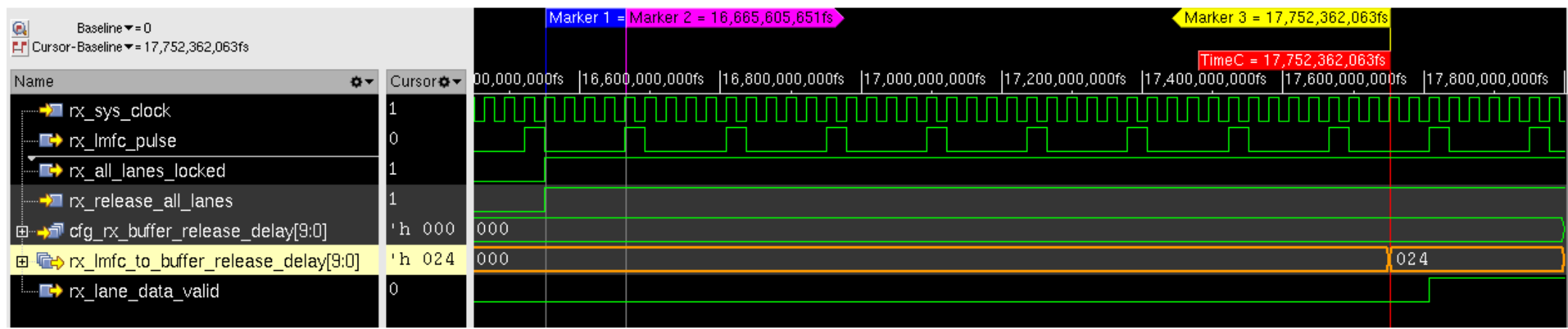
The image contains three markers pertaining to events of significance:
- Marker 1 (blue): This is the point where the Rx IP asserts its "
rx_all_lanes_locked" output signal, which consequently results in the "rx_release_all_lanes" input transitioning from 0 → 1 (explained in section 6.7). - Marker 2 (magenta): This is the subsequent LMFC boundary, where the "
rx_release_all_lanes" is recognized, initiating the lane release process in the Rx IP (and the start of the profiling counter). - Marker 3 (yellow): This is the value of the "
rx_lmfc_to_buffer_release_delay" profiling counter, indicating that it has taken 24h (36 decimal) cycles for the Rx IP to release all the lanes in a simultaneous manner. The "rx_lane_data_valid" activates exactly two cycles later.
If the same release procedure is run multiple times across power cycles and operating conditions, the release value of the profiling counter may show a variation, thereby indicating the spread of how the timing may vary. This spread can then be used to control the exact release time of the lanes, ensuring that there is no further variation.
6.8.2 Deterministic latency for systems containing one ADC and one FPGA Rx IP
The following steps should be followed for implementing robust deterministic latency for a sampling system consisting of one link between an ADC and an FPGA Rx IP.
-
The ADC and Rx IP must be aligned in terms of timing a. This means that they are all reliably sampling their corresponding SYSREF signal with their respective device clocks. i. The procedure for accurate SYSREF sampling by the Rx IP is explained in section 6.6. b. This will ensure that the ADC and FPGA Rx IP in the system are aligned in terms of their frame/multi-frame or multi-block/extended multi-block boundaries.
-
The FPGA Rx IP should have its '
cfg_rx_det_latency_en' signal tied to '1'. -
Connect the '
rx_release_all_lanes' input of the Rx IP as illustrated in section 6.7. a. For a single Rx IP case, it can be a direct connection to the 'rx_all_lanes_locked' output port. -
Force the
cfg_rx_buffer_release_delayinput of the Rx IP to 0x0. -
Determine the release point of the Rx IP using the following steps: a. Keep the Rx IP in reset by forcing its
rx_sync_resetto '1'. b. Release the IP from reset by forcingrx_sync_resetto '0'. If the ADC and Rx IP have been configured correctly, the Rx IP will initialize the link and release its lanes once the 'rx_release_all_lanes' input transitions from '0' to '1' (explained in section 6.7). i. At this point, therx_lmfc_to_buffer_release_delay(8b/10b) orrx_lemc_to_buffer_release_delay(64b/66b) will be updated by the IP. ii. This value reflects the number ofrx_sys_clockcycles needed to release the IP lanes after therx_release_all_lanesevent. c. The following image illustrates these events in time. The buffer release delay value is highlighted in orange. The yellow line indicates the delay from the event that starts the profiling counter.
-
Repeat steps in bullet 5 (above) to determine the spread of the release values for the IP. a. Note: this test should be repeated across power cycles and operating conditions in order to get a representative spread of the timing, as the number may change by a value of up to +/- 20 cycles.
-
Determine the worst case delay number across all tests in step 6, as this will become the limiting delay for guaranteeing deterministic latency.
-
Add a margin value of 2-5 cycles to the worst case delay number obtained in the previous step. For example, if the worst case number was 0x24, the final number (with the added margin) could be any value between 0x26 and 0x29.
-
Force the value of "
cfg_rx_buffer_release_delay" input of the Rx IP to the final value computed in step '8'. -
Run step 5 (above) and ensure that the IP now releases at the fixed delay value. The image below illustrates the result with the "
cfg_rx_buffer_release_delay" value forced to 0x28. It can be seen that the lane profiling counter now releases at the programmed delay.
-
Repeat step 5 across power cycles and operating conditions to ensure that this value does not change.
-
Test the overall flight time in the system by using a pulse at the front end of the ADC and monitoring the samples at the output of the Rx IP. The overall delay should remain constant.
-
You now have deterministic latency in the ADC - Rx IP link.
6.8.3 Deterministic latency for systems containing multiple ADC's and multiple FPGA Rx IP's
The following steps should be followed for implementing robust deterministic latency for a sampling system consisting of multiple ADCs and FPGA Rx IPs. The topology may be any of the following:
- Multiple ADCs connected to one Rx IP (where the Rx IP essentially sees all the ADCs as part of one link)
- Multiple ADCs connected to multiple Rx IP's in one FPGA
- Multiple ADCs connected to multiple Rx IP's across multiple FPGAs
Steps to be followed:
- The ADCs and Rx IP's must all be aligned in terms of timing. a. This means that they are all reliably sampling their corresponding SYSREF signal with their respective device clocks. i. The procedure for accurate SYSREF sampling by the Rx IP is explained in section 6.6. b. This will ensure that all the ADCs and FPGA Rx IPs in the system are aligned in terms of their frame/multi-frame or multi-block/extended multi-block boundaries.
- All FPGA Rx IPs must receive an aligned
rx_sys_clocksignal. a. This will ensure that all FPGA Rx IPs have their individual LEMC/LMFC pulse aligned across one another (depending on the encoding protocol used). - The FPGA Rx IPs should have their '
cfg_rx_det_latency_en' signal tied to '1'. - Connect the '
rx_release_all_lanes' input of all the Rx IPs as illustrated in section 6.7. This will ensure that each Rx IP initiates its lane release procedure at the same aligned LMFC/LEMC boundary. a. Note: This step is extremely important, as different IPs/links may complete their locking procedure at different points in time (and during different multi-frame / extended multi-block periods). - Force the
cfg_rx_buffer_release_delayinput of all Rx IP's to 0x0. - Determine the release point of each Rx IP using the steps explained in section 6.8.2. a. Repeat steps across power cycles and operating conditions to determine the spread of the release values for each IP.
- Determine the worst case delay number across all tests and all IPs in step 6, as this will become the limiting delay for guaranteeing deterministic latency.
- Add a margin value of 2-5 cycles to the worst case delay number obtained in the previous step. For example, if the worst case number was 0x24, the final number (with the added margin) could be any value between 0x26 and 0x29.
- Force the value of
cfg_rx_buffer_release_delayinput of all Rx IP's to the final value computed in step '8'. - Run step 5 (above) and ensure that each IP now releases at the fixed chosen value. a. Repeat steps 5 and 6 across power cycles and operating conditions to ensure that this value does not change.
- Test the overall flight time in the system by using a pulse at the front end of each ADC and monitoring the samples at the output of the corresponding Rx IP. The overall delay should remain constant, both within the link and across links.
- You now have deterministic latency in a multi ADC - multi Rx IP link.
6.8.4 Deterministic latency for systems containing one DAC and one FPGA Tx IP
The following steps should be followed for implementing robust deterministic latency for a sampling system consisting of one link between a DAC and an FPGA Tx IP.
- The DAC and Tx IP must be aligned in terms of timing. a. This means that they are all reliably sampling their corresponding SYSREF signal with their respective device clocks. i. The procedure for accurate SYSREF sampling by the Tx IP is explained in section 6.6. b. This will ensure that the DAC and FPGA Tx IP in the system are aligned in terms of their frame/multi-frame or multi-block/extended multi-block boundaries.
- Force the Tx IP's
tx_sync_resetsignal to '1'. - Force the Tx IP's
tx_sync_resetsignal to '0'. a. The Tx IP will initialize and activate the start and end sideband signals for its lanes. These signals are the frame/multi-frame (8b/10b) or multi-block/extended multi-block signals (64b/66b). b. The relevant data bytes fed to the lanes of the Tx IPs will accordingly be tagged for frame boundaries before being sent to the DAC. c. This enables the data (and samples) to be suitably re-aligned across lanes at the DAC. This alignment is ensured even if multiple lanes across arrive at different points in the time. - At this point, follow the DAC datasheet to ensure a deterministic release of its internal buffers (which will in turn control the timing of the DAC analog outputs).
6.8.5 Deterministic latency for systems containing multiple DACs and multiple FPGA Tx IPs
The following steps should be followed for implementing robust deterministic latency for a sampling system consisting of multiple DACs and FPGA Tx IPs. The topology may be any of the following:
- Multiple DACs connected to one Tx IP (where the Tx IP essentially sees all the DACs as part of one link)
- Multiple DACs connected to multiple Tx IP's in one FPGA
- Multiple DACs connected to multiple Tx IP's across multiple FPGAs
The following steps should be followed for implementing robust deterministic latency for a sampling system consisting of multiple links between DACs and FPGA Tx IPs.
- The DACs and Tx IP's must all be aligned in terms of timing. a. This means that they are all reliably sampling their corresponding SYSREF signal with their respective device clocks. i. The procedure for accurate SYSREF sampling by the Tx IP is explained in section 6.6. b. This will ensure that all the DACs and FPGA Tx IPs in the system are aligned in terms of their frame/multi-frame or multi-block/extended multi-block boundaries.
- All FPGA Tx IPs must receive an aligned
tx_sys_clocksignal. a. This will ensure that all FPGA Tx IPs have their individual LEMC/LMFC pulse aligned across one another (depending on the encoding protocol used). - All FPGA Tx IPs must receive sample/lane data that is aligned (in order for the samples to be re-aligned when extracted at the Rx end). The steps for this are: a. Monitor the LEMC/LMFC pulses across all Tx IPs to ensure that they are aligned in edge as well as phase. b. Ensure that samples that need to remain aligned through the JESD link are fed to the Tx IPs in an aligned manner. i. This is carried out by ensuring that the samples received by the various lanes of the Tx IP's on a frame/multi-frame/multi-block/extended multi-block boundary are all aligned. ii. The relevant data bytes fed to the lanes of the all Tx IPs will accordingly be tagged for frame boundaries before being sent to the DAC. iii. This enables the data (and samples) to be suitably re-aligned across lanes at the DAC. This alignment is ensured even if multiple lanes across arrive at different points in time.
- At this point, follow the DAC datasheet to ensure a deterministic release of its internal buffers (which will in turn control the timing of the DAC analog outputs).
- You will now have deterministic latency across all the DAC - Tx IP links in the system.