6.3.5 JESD204C Interface
The device uses a JESD204C high-speed serial interface for data converters to transfer data from the ADC to the receiving logic device. The device serialized lanes are capable of operating with both 8B/10B encoding and 64B or 66B encoding. The JESD204C output formats using 8B or 10B encoding are backwards compatible with existing JESD204B receivers. A maximum of 8 lanes can be used to lower lane rates for interfacing with speed-limited logic devices. There are a few differences between 8B or 10B and 64B or 66B encoded JESD204C, which is highlighted throughout this section. Figure 6-5 shows a simplified block diagram of the 8B or 10B encoded JESD204C interface and Figure 6-6 shows a simplified block diagram of the 64B or 66B encoded JESD204C interface.
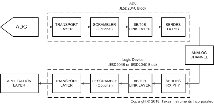
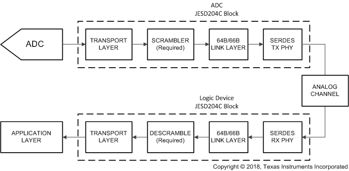
The various signals used in the JESD204C interface and the associated ADC12QJ1600-EP pin names are summarized briefly in Table 6-7 for reference. Most of the signals are common between 8B or 10B and 64B or 66B encoded JESD204C, except for SYNC which is not needed to achieve block synchronization for 64B or 66B encoding. The sync header encoded into the data stream is used for block synchronization instead of the SYNC signal.
| SIGNAL NAME | PIN NAMES | 8B/10B | 64B/66B | DESCRIPTION |
|---|---|---|---|---|
| Data | D[7:0]+, D[7:0]- | Yes | Yes | High-speed serialized data after 8B/10B or 64B/66B encoding |
| SYNC | SYNCSE | Yes | No | Link initialization signal (handshake), toggles low to start code group synchronization (CGS) process. Not used for 64B/66B encoding modes, unless it is used for NCO synchronization purposes. |
| Device clock | CLK+, CLK- or SE_CLK | Yes | Yes | ADC sampling clock or PLL reference clock, also used for clocking digital logic and output serializers |
| SYSREF | SYSREF+, SYSREF- | Yes | Yes | System timing reference used to deterministically reset the internal local multiframe clock (LMFC) or local extended multiblock clock (LEMC) counters in each JESD204C device |
Not all optional features of JESD204C are supported by ADC12QJ1600-EP. The list of features that are supported and the features that are not supported is provided in Table 6-8.
| LETTER IDENTIFIER | REFERENCE CLAUSE | FEATURE | SUPPORT IN ADC12QJ1600-EP |
|---|---|---|---|
| a | clause 8 | 8B/10B link layer | Supported |
| b | clause 7 | 64B/66B link layer | Supported |
| c | clause 7 | 64B/80B link layer | Not supported |
| d | clause 7 | The command channel when using the 64B/66B or 64B/80B link layer | Not supported |
| e | clause 7 | Forward error correction (FEC) when using the 64B/66B or 64B/80B link layer | Supported |
| f | clause 7 | CRC3 when using the 64B/66B or 64B/80B link layer | Not supported |
| g | clause 8 | A physical SYNC pin when using the 8B/10B link layer | Supported |
| h | clause 7, clause 8 | Subclass 0 | Not supported, but subclass 1 transmitter is compatible with subclass 0 receiver |
| i | clause 7, clause 8 | Subclass 1 | Supported |
| j | clause 8 | Subclass 2 | Not supported |
| k | clause 7, clause 8 | Lane alignment within a single link | Supported |
| l | clause 7, clause 8 | Subclass 1 with support for a lane alignment on a multipoint link by means of the MULTIREF signal | Not supported |
| m | clause 8 | SYNC interface timing is compatible with JESD204A | Supported |
| n | clause 8 | SYNC interface timing is compatible with JESD204B | Supported |
1 Transport Layer
The transport layer takes samples from the ADC output and maps the samples into octets inside of frames. These frames are then mapped onto the available lanes. The mapping of octets into frames and frames onto lanes is defined by the transport layer settings such as L, M, F, S, N and N'. An octet is 8 bits (before 8B/10B or 64B/66B encoding), a frame consists of F octets and the frames are mapped onto L lanes. Samples are N bits, but sent as N' bits across the link. The samples come from M converters and there are S samples per converter per frame cycle. M is sometimes artificially increased in order to obtain a more desirable mapping, for instance lower latency may be achieved with a larger M value for long frames.
There are a number of predefined transport layer modes in the device that are defined in Table 6-15. The high level configuration parameters for the transport layer in the device are described in Table 6-13. The transport layer mode is chosen by simply setting the JMODE register setting. For reference, the various configuration parameters for JESD204C are defined in Table 6-14.
The link layer further maps the frames into multiframes when using 8B/10B encoding or blocks, multiblocks and extended multiblocks when using 64B/66B encoding.
2 Scrambler
A data scrambler is available to scramble the data before transmission across the channel. Scrambling is used to remove the possibility of spectral peaks in the transmitted data due to repetitive data streams. The scrambler is optional for 8B or 10B encoded modes, however it is mandatory for 64B or 66B encoded modes in order to have sufficient spectral content for clock recovery and adaptive equalization. The scrambler operates on the data before encoding, such that the 8B or 10B scrambler scrambles the 8-bit octets before 10-bit encoding and the 64B or 66B scrambler scrambles the 64-bit block before the sync header insertion (66-bit encoding). The JESD204C receiver automatically synchronizes its descrambler to the incoming scrambled data stream. For 8B/10B encoding, the initial lane alignment sequence (ILA) is never scrambled. Scrambling can be enabled by setting SCR for 8B or 10B encoding modes, but it is automatically enabled in 64B/66B modes. The scrambling polynomial is different for 8B or 10B encoding and 64B or 66B encoding schemes as defined by the JESD204C standard.
3 Link Layer
The link layer serves multiple purposes in JESD204C for both 8B or 10B and 64B or 66B encoding schemes, however there are some differences in implementation for each encoding scheme. In general, the link layer responsibilities include scrambling of the data see (Scrambler), establishing the code (8B or 10B) or block (64B or 66B) boundaries and the multiframe (8B or 10B) or multiblock (64B or 66B) boundaries, initializing the link, encoding the data, and monitoring the health of the link. This section is split into an 8B or 10B section (8B or 10B Link Layer) and a 64B or 66B section (64B-66B-Link-Layer) in order to cover the specific implementation for each encoding scheme.
4 8B or 10B Link Layer
This section covers the link layer for the 8B or 10B encoding operating modes including initialization of the character, frame and multiframe boundaries, alignment of the lanes, 8B or 10B encoding and monitoring of the frame and multiframe alignment during operation.
4.1 Data Encoding (8B or 10B)
The data link layer converts the 8-bit octets from the transport layer into 10-bit characters for transmission across the link using 8B or 10B encoding. 8B or 10B encoding ensures DC balance to allow use of AC-coupling between the SerDes transmitter and receiver and specify a sufficient number of edge transitions for the receiver to reliably recover the data clock. 8B/10B encoding also provides some error detection since a single bit error in a character likely results in either not being able to find the 10-bit character in the 8B or 10B decoder lookup table or an incorrect character disparity.
4.2 Multiiframes and the Local Multiframe Clock (LMFC)
The frames from the transport layer are combined into multiframes which are used in the process of achieving deterministic latency in subclass 1 implementations. The length of a multiframe is set by the K parameter which defines the number of frames in a multiframe. JESD204C increases the maximum allowed number of frames per multiframe (K) from 32 in JESD204B to 256 in JESD204C to allow a longer multiframe to ease deterministic latency requirements. The total allowed range of K is defined by the inequality ceil(17/F) ≤ K ≤ min(256, floor(1024/F)) where ceil() and floor() are the ceiling and floor function, respectively. The local multiframe clock (LMFC) keeps track of the start and end of a multiframe for deterministic latency and data synchronization purposes. The LMFC is reset by the SYSREF signal to a deterministic phase in both the transmitter and receiver in order to act as a timing reference for deterministic latency. The LMFC clock frequency is given in Equation 8 where fBIT is the serialized bit rate (line rate) of the SerDes interface and F and K are as defined above. The frequency of SYSREF must equal to or an integer division of fLMFC when using 8B/10B encoding modes if SYSREF is a continuous signal.
Equation 8: fLMFC = fBIT / (10 x F x K)
4.3 Code Group Synchronization (CGS)
The first step in initializing the JESD204C link, after the LMFC is deterministically reset by SYSREF, is for the receiver to find the boundaries of the encoded 10-bit characters sent across each SerDes lane. This process is called code group synchronization (CGS). The receiver first asserts the SYNC signal (set to logic '0') when ready to initialize the link. The transmitter responds to the request by sending a stream of K28.5 comma characters. The receiver aligns its character clock to the K28.5 character sequence and CGS is achieved after successfully receiving four consecutive K28.5 characters. The receiver deasserts SYNC (set to logic '1') on the next LMFC edge after CGS is achieved and waits for the transmitter to start the initial lane alignment sequence (ILAS).
4.4 Initial Lane Alignment Sequence (ILAS)
After the transmitter detects the SYNC signal deassert (logic '0' to logic '1' transition), the transmitter waits until its next LMFC edge to start sending the initial lane alignment sequence (ILAS). The ILAS consists of four multiframes each containing a predetermined sequence. The receiver searches for the start of the ILAS to determine the frame and multiframe boundaries. Each multiframe of the ILAS starts with a /R/ character (K28.0) and ends with a /A/ character (K28.3) and either can be used to detect the boundary of a multiframe. Each lane starts buffering its data in the elastic buffer once the ILAS reaches the receiver, starting with the /R/ character, until all receivers have received the ILAS and subsequently release the ILAS from all lanes at the same time in order to align the lanes. The elastic buffer release point is chosen to avoid ambiguity in the release of the data caused by variation in the data delay (arrival of the ILAS at the receiver for each lane). The second multiframe of the ILAS contains configuration parameters for the JESD204C link configuration that can be used by the receiver to verify that the transmitter and receiver configurations match.
4.5 Frame and Multiframe Monitoring
The device supports frame and multiframe monitoring for verifying the health of the JESD204C link when using 8B/10B encoding. The scheme changes depending on the use of scrambling. The implementation when scrambling is disabled is covered first. If the last octet of the current frame matches the last octet of the previous frame, then the last octet of the current frame is encoded as an /F/ (K28.7) character. If the current frame is also the last frame of a multiframe, then an /A/ (K28.3) character is used instead. Neither an /F/ or /A/ character should occur in a normal data stream, except when replaced by the transmitter for alignment monitoring. When the receiver detects an /F/ or /A/ character in the normal data stream the receiver checks to see if the character occurs at the location expected to be the end of a frame or multiframe. If the character occurs at a location other than the end of a frame or multiframe then either the transmitter or receiver has become misaligned. The receiver replaces the alignment character with the appropriate data character upon reception of a properly aligned /F/ or /A/ character. The appropriate data character is the last octet of the previously received frame. This scheme increases the probability of an alignment character for non-scrambled data streams.
The implementation when scrambling is enabled is slightly different since the octets are randomized. If the last octet of a frame is 0xFC (before 8B/10B encoding) then the transmitter encodes the octet as an /F/ (/K28.7/) character. If the last octet of a multiframe is 0x7C (before 8B/10B encoding) then the transmitter encodes the octet as an /A/ (/K28.3/) character. The location of the /A/ and /F/ characters is monitored to verify proper frame and multiframe alignment. The receiver replaces the alignment characters by simply replacing an /F/ character with the 0xFC octet and an /A/ character with the 0x7C octet.
The receiver can report an error if multiple alignment characters occur in the incorrect location or do not occur when expected. Upon detection of a frame or multiframe misalignment, the receiver should trigger a link realignment by asserting SYNC. SYSREF should also be reissued to verify that the LMFC in the transmitter and receiver have proper alignment before restarting the link.
5 64B or 66B Link Layer
This section covers the link layer for the 64B or 66B encoding operating modes which includes scrambling of the data, addition of the sync headers (64B or 6B encoding), the structure of the block and multiblock, the sync header, cyclic redundancy checking (CRC), forward error correction (FEC) and link alignment.
5.1 64B or 66B Encoding
The frames formed by the transport layer are packed into 8-octet long blocks (64 bits). This 64-bit block is scrambled and then a 2-bit sync header (SH) is appended to form a 66-bit transmission block. The sync header is used for block synchronization by marking the end of a block as well as allowing for cyclic redundancy checking (CRC), forward error correction (FEC) or a command channel. The structure of a block is given in Table 6-9 where SH represents the appended 2-bit sync header.
| SH | OCTET0 | OCTET1 | OCTET2 | OCTET3 | OCTET4 | OCTET5 | OCTET6 | OCTET7 |
|---|---|---|---|---|---|---|---|---|
| [0:1] | [2:9] | [10:17] | [18:25] | [26:33] | [34:41] | [42:49] | [50:57] | [58:65] |
5.2 Multiblocks, Extended Multiblocks and the Local Extended Multiblock Clock (LEMC)
A multiblock is a 32 block container which consists of a concatenation of 32 blocks. An extended multiblock is a concatenation of multiple multiblocks, where E defines the number of multiblocks in an extended multiblock. A frame can be split between blocks and multiblocks, but there must be an integer number of frames in an extended multiblock. An extended multiblock is only necessary when a multiblock does not have an integer number of frames. If an extended multiblock is not used, because a multiblock contains an integer number of frames, then the E parameter is equal to 1 to indicate that there is one multiblock in an extended multiblock.
An extended multiblock is analogous to a multiframe in the 8B or 10B transport layer. The local extended mutiblock clock (LEMC) keeps track of the start and end of a multiblock for deterministic latency and data synchronization purposes in the same way the LMFC tracks the start and end of a multiframe in 8B or 10B encoding. The LEMC is reset by the SYSREF signal to a deterministic phase in both the transmitter and receiver in order to act as a timing reference for deterministic latency. The LEMC clock frequency is defined by Equation 9 where fBIT is the serialized bit rate (line rate) of the SerDes interface. The frequency of SYSREF must equal to or an integer division of fLMFC when using 64B or 66B encoding modes if SYSREF is a continuous signal.
Equation 9. fLEMC = fBIT / (66 x 32 x E)
5.2.1 Block, Multiblock and Extended Multiblock Alignment using Sync Header
The sync header contains two bits that are always opposite of each other (either 01 or 10). The JESD204C receiver can find the block boundaries by looking for a 66-bit boundary that always contains a 0 to 1 or 1 to 0 transition. Although 0 to 1 and 1 to 0 transitions occur at other locations in a block, it is impossible for the sequence to appear at a fixed location, other than the proper sync header location, in successive blocks for a long period of time. The sync header indicates the start of a block and can be used for block alignment monitoring. If a 00 or a 11 bit sequence is seen at the assumed sync header location of a block, then block alignment may have been lost. Multiple occurrences of incorrect sync header bits should trigger a search for the sync header after sending SYSREF to all devices to reset LEMC alignment.
A sync header ([0:1]) of 01 corresponds to transmission of a 1 while a sync header of 10 corresponds to a transmission of a 0. The transmitted bit from the sync header of each block of a multiblock are combined into a 32-bit word called the sync header stream. The sync header stream is used to transmit data in parallel with the user data in order to synchronize the link by marking the borders of multiblocks and extended multiblocks. In addition, the sync header stream provides one of either CRC, FEC or a command channel. ADC12QJ1600-EP supports CRC-12 and FEC and does not support CRC-3 or the command channel.
The 32-bit sync header stream always ends with a 00001 bit sequence, called the end-of-multiblock (EoMB) signal, that indicates the end of a multiblock. For CRC and command channel modes, a 00001 sequence never occur in any other location in the sync header stream. For FEC mode, it is possible for a 00001 sequence to appear in another location within the sync header stream, however it is improbable to see the 00001 sequence in the same location within a sequence of multiple multiblocks. Therefore, in FEC mode it may take more than one multiblock to find the end of a multiblock. The end of an extended multiblock is found for all modes by monitoring bit 22 of the sync header stream, the EoEMB bit, which indicates the end of an extended multiblock when set to a 1. The EoMB (00001) and EoEMB signals, as well as fixed 1s in the sync header stream for CRC and command channel modes, form the pilot signal of the sync header stream.
The defined format for each form of the sync header stream are defined in the following sections.
5.2.1.1 Cyclic Redundancy Check (CRC) Mode
The cyclic redundancy check (CRC) mode is available to allow detection of potential bit errors during transmission. Support for the 12-bit word CRC-12 mode is required by JESD204C, while a 3-bit word CRC-3 mode is optional. The device does not support the CRC-3 mode and therefore this section is specific to the CRC-12 mode only. The transmitter computes the CRC-12 parity bits from the scrambled data bits of the 32 blocks of a multiblock. The 12-bit CRC parity word is then transmitted in the sync header stream of the next multiblock. The receiver computes the 12-bit parity word of the received multiblock and compares it against the received 12-bit parity word of the next multiblock. A difference indicates that there is at least one error in the received data bits or in the received 12-bit parity word. The minimum latency to the detection of a bit error in the first data bit of a multiblock is 46 blocks. Enable CRC-12 mode by setting SHMODE to 0.
The mapping of the sync header stream when using the CRC-12 mode is shown in Table 6-10. CRC[x] corresponds to bit x of the 12-bit CRC word. Cmd[x] corresponds to bit x of the 7 bit command word, which are always set to 0s in the device. The 00001 bit sequence at the end of the sync header stream is the pilot signal that is used to identify the end of a multiblock. The 1s that occur throughout the sync header ensure that the pilot signal can only be seen at the end of the sync header, allowing multiblock alignment after only a single multiblock has been received. EoEMB is the end-of-extended-multiblock bit, which is set to 1 for the last multiblock of an extended multiblock.
| Bit | Function | Bit | Function | Bit | Function | Bit | Function |
|---|---|---|---|---|---|---|---|
| 0 | CRC[11] | 8 | CRC[5] | 16 | Cmd[6] | 24 | Cmd[2] |
| 1 | CRC[10] | 9 | CRC[4] | 17 | Cmd[5] | 25 | Cmd[1] |
| 2 | CRC[9] | 10 | CRC[3] | 18 | Cmd[4] | 26 | Cmd[0] |
| 3 | 1 | 11 | 1 | 19 | 1 | 27 | 0 |
| 4 | CRC[8] | 12 | CRC[2] | 20 | Cmd[3] | 28 | 0 |
| 5 | CRC[7] | 13 | CRC[1] | 21 | 1 | 29 | 0 |
| 6 | CRC[6] | 14 | CRC[0] | 22 | EoEMB | 30 | 0 |
| 7 | 1 | 15 | 1 | 23 | 1 | 31 | 1 |
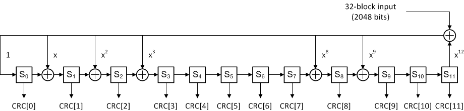
The CRC-12 encoder takes in a multiblock of 32 scrambled blocks (2048 bits) and computes the 12-bit parity word using the generator polynomial given by Equation 10. The polynomial is sufficient to detect all 2-bit errors in a multiblock, spanning any distance, and burst error sequences of up to 12-bits in length. The probability of not detecting a 3-bit error spanning any distance in a multiblock is approximately 0.004%.
Equation 10: 0x987 == x12 + x9 + x8 + x3 + x2 + x + 1
The full parity bit generation for CRC-12 is shown in Figure 6-7. The input is a 2048 bit sequence, built from the 32 scrambled blocks of a multiblock (sync header is not included). The 12-bit parity word, CRC[11:0], is taken from the Sx blocks after the full 2048 bit sequence is processed. The Sx blocks are initialized with 0s before processing each multiblock. For more information on the CRC-12 parity word generation, refer to the JESD204C standard.
5.2.1.2 Forward Error Correction (FEC) Mode
Forward error correction (FEC) is an optional feature in JESD204C and is supported by ADC12QJ1600-EP. Whereas CRC-12 mode can only detect errors on the link, FEC is able to detect and correct errors in order to improve the bit error rate (BER) for error-sensitive applications. Many applications can tolerate random bit errors, however some applications, such as an oscilloscope, rely on long error-free measurements in order to detect a certain response from the device under test (DUT). An error in these applications may result in a false-positive detection of the response. Enable FEC mode by setting SHMODE to 2.
A scrambled multiblock of 32 blocks (2048 bits) is input into the FEC parity bit generator to generate the 26-bit parity word. The parity word is sent in the sync header stream of the next multiblock. The receiver then calculates its own 26-bit parity word and calculates the difference between the locally generated and received parity word, called the syndrome of the received bits. If the syndrome is 0, then all bits are assumed to have been received correctly, while any value other than 0 indicates at least one error in either the data bits or the parity word. If the syndrome is non-zero, then it can be used to determine the most likely error and then correct the error. The minimum latency from a bit error to detection and correct of a bit error in the first bit of a multiblock is 58 blocks.
The mapping of the sync header stream when using FEC mode is shown in Table 6-11. FEC[x] corresponds to bit x of the 26-bit FEC word. The 00001 bit sequence at the end of the sync header stream is the pilot signal that is used to identify the end of a multiblock. It is possible for a 00001 sequence to appear in another location within the sync header stream in FEC mode, however it is improbable to see the 00001 sequence in the same location within a sequence of multiple multiblocks. Therefore, in FEC mode it may take more than one multiblock to find the end of a multiblock. EoEMB is the end-of-extended-multiblock bit, which is set to 1 for the last multiblock of an extended multiblock.
| Bit | Function | Bit | Function | Bit | Function | Bit | Function |
|---|---|---|---|---|---|---|---|
| 0 | FEC[25] | 8 | FEC[17] | 16 | FEC[9] | 24 | FEC[2] |
| 1 | FEC[24] | 9 | FEC[16] | 17 | FEC[8] | 25 | FEC[1] |
| 2 | FEC[23] | 10 | FEC[15] | 18 | FEC[7] | 26 | FEC[0] |
| 3 | FEC[22] | 11 | FEC[14] | 19 | FEC[6] | 27 | 0 |
| 4 | FEC[21] | 12 | FEC[13] | 20 | FEC[5] | 28 | 0 |
| 5 | FEC[20] | 13 | FEC[12] | 21 | FEC[4] | 29 | 0 |
| 6 | FEC[19] | 14 | FEC[11] | 22 | EoEMB | 30 | 0 |
| 7 | FEC[18] | 15 | FEC[10] | 23 | FEC[3] | 31 | 1 |
The FEC encoder takes in a multiblock of 32 scrambled blocks (2048 bits) and computes the 26-bit parity word using the generator polynomial given by Equation 11. The 2048 scrambled input bits plus 26 parity bits forms a shortened (2074, 2048) binary cyclic code. The (2074, 2048) binary cyclic code is shortened from the cyclic Fire code (8687, 8661). This polynomial can correct up to a 9-bit burst error per multiblock.
Equation 11. g(x) = (x17+1)(x9+x4+1) == x26+x21+x17+x9+x4+1 The full 26-bit FEC parity word generation is shown in Figure 6-8. The input is a 2048 bit sequence, built from the 32 scrambled blocks of a multiblock (sync header is not included). The 26-bit parity word, FEC[25:0], is taken from the Sx blocks after the full 2048 bit sequence is processed. The Sx blocks are initialized with 0s before processing each multiblock. For more information on the FEC parity word generation, refer to the JESD204C standard.
5.3 Initial Lane Alignment
The 64B or 66B link layer does not use an initial lane alignment sequence (ILAS) like the 8B/10B link layer. Therefore, the receiver must use a different scheme to align lanes using the elastic buffer. In 8B or 10B mode, the ILAS triggers the elastic buffer to start buffering the data for each lane. After all lanes have started buffering the data, the elastic buffers for each lane are released at a release point determined by the release buffer delay (RBD) parameter and the phase of the LMFC. In 64B/66B mode, the process starts by having all lanes achieve block, multiblock and extended multiblock alignment. Once all lanes have achieved alignment, the receiver can begin buffering data in the elastic buffers at the start of the next extended multiblock on each lane. The data is released at the next release point after all lanes have seen the start of an extended multiblock and have started buffering the data. The release point is defined relative to the LEMC edge and the programmed RBD value, the most intuitive of which is to release on the LEMC edge itself. The release point must be chosen to avoid the region of the LEMC containing variation in the data delay on each lane from startup to startup.
5.4 Block, Multiblock and Extended Multiblock Alignment Monitoring
Synchronization of blocks, multiblocks and extended multiblocks by monitoring the sync header of each block and EoMB and EoEMB bit of the sync header stream. A block always begins with a 0 to 1 or 1 to 0 transition (sync header). A single missed sync header can occur due to a bit error, however if there are a number of sync header errors within a set number of blocks, then block synchronization has been lost and block synchronization should be reinitialized. It is possible to still have block synchronization, but to lose multiblock or extended multiblock synchronization. Multiblock synchronization is monitored by looking for the EoMB signal, 00001, at the end of the sync header stream for each multiblock. If multiple EoMB signals are erroneous within a number of blocks, multiblock synchronization has been lost and multiblock synchronization should be reinitialized. If an erroneous EoEMB bit is received for multiple extended multiblocks within a number of extended multiblocks, such as a 1 for a multiblock that is not the end of an extended multiblock or a 0 for a multiblock that is the end of an extended multiblock, then multiblock synchronization is lost and extended multiblock synchronization should be reinitialized. If multiblock or extended multiblock synchronizaton is lost, SYSREF should be applied to the erroneous devices in order to reestablish the LEMC before the synchronization process begins.
6 Physical Layer
The JESD204C physical layer consists of a current mode logic (CML) output driver and receiver. The receiver consists of a clock detection and recovery (CDR) unit to extract the data clock from the serialized data stream and can contain a continuous time linear equalizer (CTLE) and/or discrete feedback equalizer (DFE) to correct for the low-pass response of the physical transmission channel. Likewise, the transmitter can contain pre-equalization to account for frequency dependent losses across the channel. The total reach of the SerDes links depends on the data rate, board material, connectors, equalization, noise and jitter, and required bit-error performance. The SerDes lanes do not have to be matched in length because the receiver aligns the lanes during the initial lane alignment sequence.
6.1 SerDes Pre-Emphasis
The ADC12QJ1600-EP high-speed output drivers can pre-equalize the transmitted data stream by using pre-emphasis in order to compensate for the low-pass response of the transmission channel. Configurable pre-emphasis settings allow the output drive waveform to be optimized for different PCB materials and signal transmission distances. The pre-emphasis setting is adjusted through the serializer pre-emphasis setting SER_PE. Higher values increase the pre-emphasis to compensate for more lossy PCB materials. This adjustment is best used in conjunction with an eye-diagram analysis capability in the receiver. Adjust the pre-emphasis setting to optimize the eye-opening for the specific hardware configuration and line rates needed.
7 JESD204C Enable
The JESD204C interface must be disabled through JESD_EN while any of the other JESD204C parameters are being changed. When JESD_EN is set to 0 the block is held in reset and the serializers are powered down. The clocks for this section are also gated off to further save power. When the parameters are set as desired, the JESD204C block can be enabled (JESD_EN is set to 1).
8 Multi-Device Synchronization and Deterministic Latency
JESD204C subclass 1 outlines a method to achieve deterministic latency across the serial link. If two devices achieve the same deterministic latency then they can be considered synchronized. This latency must be achieved from system startup to startup to be deterministic. There are two key requirements to achieve deterministic latency. The first is proper capture of SYSREF for which the device provides a number of features to simplify this requirement at giga-sample clock rates (see the SYSREF Capture for Multi-Device Synchronization and Deterministic Latency section for more information). SYSREF resets either the LMFC in 8B/10B encoding mode or the LEMC is 64B/66B encoding mode. The LMFC and LEMC are analogous between the two modes and is now referred to as LMFC/LEMC.
The second requirement is to choose a proper elastic buffer release point in the receiver. Because the device is an ADC, the device is the transmitter (TX) in the JESD204C link and the logic device is the receiver (RX). The elastic buffer is the key block for achieving deterministic latency, and does so by absorbing variations in the propagation delays of the serialized data as the data travels from the transmitter to the receiver. A proper release point is one that provides sufficient margin against delay variations. An incorrect release point results in a latency variation of one LMFC/LEMC period. Choosing a proper release point requires knowing the average arrival time of data at the elastic buffer, referenced to an LMFC/LEMC edge, and the total expected delay variation for all devices. With this information the region of invalid release points within the LMFC/LEMC period can be defined, which stretches from the minimum to maximum delay for all lanes. Essentially, the designer must ensure that the data for all lanes arrives at all devices after the previous release point occurs and before the next release point occurs.
Figure 6-9 provides a timing diagram that demonstrates this requirement. In this figure, the data for two ADCs is shown. The second ADC has a longer routing distance (tPCB) and results in a longer link delay. First, the invalid region of the LMFC/LEMC period is marked off as determined by the data arrival times for all devices. Then, the release point is set by using the release buffer delay (RBD) parameter to shift the release point an appropriate number of frame clocks from the LMFC/LEMC edge so that the release point occurs within the valid region of the LMFC/LEMC cycle. In the case of Figure 6-9, the LMFC/LEMC edge (RBD = 0) is a good choice for the release point because there is sufficient margin on each side of the valid region.
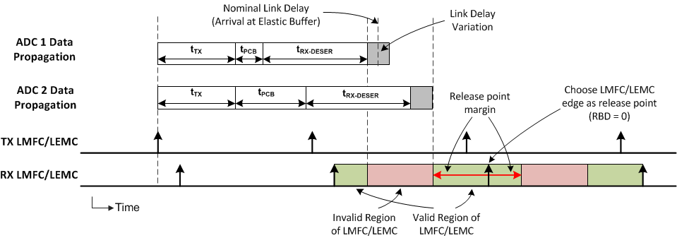
The TX and RX LMFC/LEMCs do not necessarily need to be phase aligned, but knowledge of their phase is important for proper elastic buffer release point selection. Also, the elastic buffer release point occurs within every LMFC/LEMC cycle, but the buffers only release when all lanes have arrived. Therefore, the total link delay can exceed a single LMFC/LEMC period; see JESD204B multi-device synchronization: Breaking down the requirements for more information.
9 Operation in Subclass 0 Systems
The device can operate with subclass 0 compatibility provided that multi-ADC synchronization and deterministic latency are not required. With these limitations, the device can operate without the application of SYSREF. The internal LMFC/LEMC is automatically self-generated with unknown timing. SYNC is used as normal to initiate the CGS and ILAS in 8B/10B mode.
10 Alarm Monitoring
A number of built-in alarms are available to monitor internal events. Several types of alarms and upsets are detected by this feature:
C-PLL is not locked S-PLL is not locked JESD204C link is not transmitting data (not in the data transmission state) SYSREF causes internal clocks to be realigned An upset that impacts the internal clocks A read or write error generated by the digital to serializer synchronizing FIFO When an alarm occurs, a bit for each specific alarm is set in ALM_STATUS. Each alarm bit remains set until the host system writes a 1 to clear the alarm. If the alarm type is not masked (see the ALM_MASK register), then the alarm is also indicated by the ALARM register. The CALSTAT output pin can be configured as an alarm output that goes high when an alarm occurs; see CAL_STATUS_SEL.
10.1 Clock Upset Detection
The CLK_ALM register bit indicates if the internal clocks have been upset. The clocks in channel A are continuously compared to channel B. If the clocks differ for even one DEVCLK / 2 cycle, the CLK_ALM register bit is set and remains set until cleared by the host system by writing a 1. For the CLK_ALM register bit to function properly, follow these steps:
Program JESD_EN = 0 Ensure the part is configured to use both channels (PD_ACH = 0, PD_BCH = 0) Program JESD_EN = 1 Write CLK_ALM = 1 to clear CLK_ALM Monitor the CLK_ALM status bit or the CALSTAT output pin if CAL_STATUS_SEL is properly configured When exiting global power-down (via MODE or the PD pin), the CLK_ALM status bit may be set and must be cleared by writing a 1 to CLK_ALM
10.2 FIFO Upset Detection
The FIFO_LANE_ALM register bits indicate if an error has occurred in the synchronizing FIFO between the digital logic block and serializer outputs. If the FIFO pointers are upset due to an undesired clock shift or other single event or incorrect clocking frequencies the FIFO_LANE_ALM bit for the erroneous lane is set to 1. Toggling JESD_EN to 0 and then 1 resets the FIFO logic.